|
||||||||||||||||||||
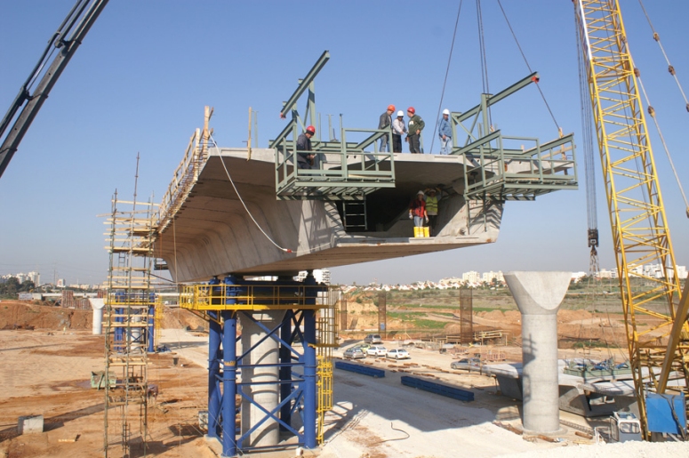
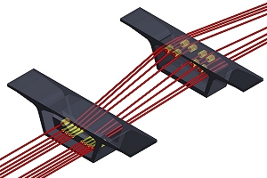
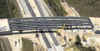
Design and Construction Challenges The contractor, Danya Cebus, Ltd., was challenged with a tight construction schedule to meet concession agreement requirements and project financing goals. As a result, FEG proposed the use of external tendons to allow for simplified precasting of the segments, reduction in segment cross-sectional area and foundation loads, fewer tendon stressing operations and a reduced design schedule. FEG worked with the contractor during a streamlined final design process that began in February 2006 and resulted in the casting of the first segment in July of the same year. The project involves many challenges commonly seen in today�s construction environment, including a rapid construction schedule and budgetary restrictions. The contractor also required details that enhanced the long-term durability of the structure because they must own and maintain these bridges in satisfactory condition for 30 years before transferring ownership to the government. Due to the span lengths and size of the segments, FEG�s technical director, Jacques Combault, proposed a combination of internal and external tendons to maximize the efficiency of these precast box girder bridges. Internal tendons are used in the top slab in support of the crane-based balanced cantilever construction, and external tendons are utilized for all continuity post-tensioning. This system was developed with the contractor for more consistent segment precasting configurations, rapid installation of continuity tendons and fewer tendon stressing operations.
The design process included a technical review by Israeli General Consultant engineers to confirm that the external tendon system adequately met the project requirements. To assist the Israeli engineers in evaluating external tendon post-tensioning systems, FEG produced a technical white paper that included details of previous projects, excerpts from technical articles, and a list of benefits that the external tendons bring to the project. It also included FEG�s analysis of tendon loss scenarios to meet strict bridge security requirements and design methodology for service and ultimate limit state design with external tendons. External tendon benefits The use of external tendons also provided technical advantages in the bridge design, such as increased ductility for flexural moment resistance and a significant reduction in principle tensile stresses in the box girder webs. These benefits allowed for longer, constant-depth span lengths for the bridges while still meeting the interchange design requirements. "The large anchorage zones required for external tendons presented a challenge in keeping the pier segment weight within the 65 tonne lifting capacity of the contractor�s equipment ", said Craig Finley, President of Finley Engineering Group, "but by using LUSAS we easily modified complex shapes and efficiently optimized the internal pier segment dimensions". Along with the introduction of external tendons, FEG incorporated several other innovations on this project, including the use of diabolos in the pier segments and deviators to simplify the external tendon details. These post-tensioning details allow for replacement of the external tendons should this be required in the future. FEG also specified the use of pre-packaged grouts, multiple levels of protection and enhanced duct systems to improve post-tensioning system performance.
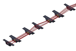
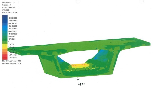
Jerry Pfuntner, Principal Engineer at FEG said: "The segment models created with LUSAS Bridge helped the Israeli design reviewers to feel comfortable with the external tendon details. The models showed the stress levels in the box girder webs, bottom and top slabs as a result of the external deviation forces. This helped FEG to obtain approval and assure all parties that these details would work well under service load conditions".
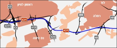
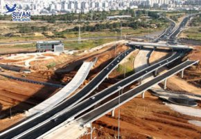
In summary The use of external tendons on a segmental bridge project is not a revolutionary concept. But, by assessing the contractor�s needs and introducing proven segmental bridge technologies to the Israeli construction practice, this approach by FEG provided recognized benefits to the owner and contractor with simplified precasting details, rapid erection procedures and improved long-term durability. Design of the bridges on this interchange of the Road 431 project offers another case study in the benefits of meeting challenges by seeking solutions that go beyond standard practice and "conventional wisdom". "LUSAS Bridge has been a great tool for us on this project. It allowed us to produce a design that has major benefits for the client and contractor. We would recommend its use to others wanting to enhance their in-house design and analysis capabilities". Craig Finley, President, Finley Engineering Group Inc. Share this article
Find out more
Other LUSAS Bridge case studies:
|
|
Software Information
|
||||||||||||||||||
|