Engineering analysis + design software

User Area > Advice

Using joints: Mesh attributes

Using Joints: Mesh  |  Geometric attributes  |  Material attributes  |  Spring stiffnesses  |  Supports  |  Loadcase properties

The joint element mesh attribute used in a model controls which degrees of freedom (DOF) will be available to be partially restrained. In essence, the DOF in the joint should match the DOF in the elements to which it will be connected.  Mesh attributes appropriate to common uses of joints are described below; full information on all available joint elements is given in the help menu:

Help topics > Element Reference Manual > Chapter 8 : Joint Elements

See also:

Help topics > Element Reference Manual > Appendix L : Joint Element Compatibility

It is prudent always to use a local coordinate dataset to control the element axes for joints.  This can be specified on assignment of the joint mesh, and so must be defined beforehand; assigning it to the feature later will NOT reorientate the element.  For many analyses it is probably easiest to use a local coordinate=global coordinate which may be defined using the menu item:

Attributes > Local coordinate...
Attributes > Local Coordinate > (pick) Cartesian (pick) Rotate (enter text box) Angle=0

Mesh attributes for joints between point features

The appropriate joint mesh for use in a 2D frame model is generally "joint for beams 2D" (JPH3). The appropriate joint mesh for use in a 3D frame model is generally "joint for beams 3D" (JSH4). 

In some instances, however, it may be more appropriate to use "joint no rotational stiffness" (JNT3 or JNT4) when no rotational stiffness is required. This is simpler than using JPH3 or JSH4 as the rotational stiffnesses do not need to be input as zero or a small number. 

A JNT3 or JNT4 mesh may be defined using the menu item:

Attributes > Mesh > Point > Point Mass or Joint...

(drop down menus) Structural element type = Joint no rotational stiffness, Number of dimensions = [select 2D or 3D as appropriate]

There should be only 1 division in the mesh definition.

You may assign the mesh by selecting two points to create a joint between and assign the joint mesh attribute by dragging and dropping it from the Attributes TreeView onto the model in the graphics window.

Alternatively, the mesh may be assigned by selecting a set of points with your mouse and adding it to the selection memory. Then separately select a second set of points in normal selection and assign the joint mesh. This will create a series of joints between nodes paired between the two selected sets, in the order selected or the point number order (if box selected).  
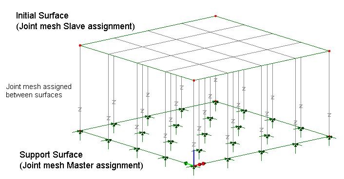
If the option "Mesh from master to slave" is ticked, then the points in normal selection will become the 'Master' assignments to which material and geometric attributes for the joint are then to be assigned. The points in the selection memory will become salve points.

When you assign the mesh attribute you are able to specify a local coordinate dataset if one is already defined (recommended approach for controlling joint local axes).

Mesh attributes for joints between line features (or edges of surfaces)

The appropriate mesh to connect to all 6 degrees of freedom in thin shells (QSI4), thick shells (QTS4, QTS8) and 3D beam elements is "joint for beams 3D" (JSH4).  In some instances if no rotational stiffness is required it may be more appropriate to use "joint no rotational stiffness" (JNT4).  This is simpler than using JSH4 as the rotational stiffnesses do not need to be input as zero or a small number. 

A JNT3 mesh may be defined using the menu item:

Attributes > Mesh > Line...

(drop down menus) Structural element type = Joint no rotational stiffness, Number of dimensions = [select 2D or 3D as appropriate]

The mesh definition should include the number of divisions you want on the relevant side of the surface features you are joining.  For plate, plane stress or plane strain models, an appropriate 2-dimensional joint should be selected.

You may assign the mesh by selecting one line (or a set of lines) with your mouse and adding it to the selection memory. Then select the second line (or a set of lines) with your mouse and assign the joint mesh attribute by dragging and dropping it from the Attributes TreeView onto the model in the graphics window.

When you assign the mesh attribute you are able to specify a local coordinate dataset if one is already defined (recommended approach for controlling joint local axes).


Mesh attributes for joints between faces of surface features

The mesh which should be assigned between the faces of surface features is generally "joint no rotational stiffness" (JNT4 for solids), obtained using the menu item:

Attributes > Mesh > Surface...

(drop down menus) Structural element type = Joint no rotational stiffness

For joints between shells you may use JSH4 (with rotational stiffness) or JNT4 if no rotational stiffness is required.

You can control the mesh divisions in the normal way (e.g. using null line meshes) but you should ensure that the mesh divisions on the surfaces used are identical.

You may assign the mesh by selecting one surface (or a set of surfaces) with your mouse and adding it to the selection memory. Then select the second surface (or a set of surfaces) with your mouse and assign the joint mesh attribute by dragging and dropping it from the TreeView onto the model in the graphics window.  When you assign the mesh attribute you are able to specify a local coordinate dataset if one is defined (recommended). 

For the example where joints are used to allow lift-off from a support surface, the surfaces used should be the "support surface" and "initial surface" as shown in this image.  Read more about features required for joints on faces of surface features

You may check element axes using:

TreeView > Layers tab > Mesh > (check) Show element axes

More information on local coordinates may be found in the help menu item:

Help > Help Topics > Contents > Modeller Reference Manual > Chapter 5 : Model Attributes > Other Attributes > Local Coordinates


How do I model lift off supports? (main page)

How do I model tension only members? (main page)

How do I model a hinged connection between shell meshed surfaces? (main page)


innovative | flexible | trusted

LUSAS is a trademark and trading name of Finite Element Analysis Ltd. Copyright 1982 - 2022. Last modified: November 29, 2022 . Privacy policy. 
Any modelling, design and analysis capabilities described are dependent upon the LUSAS software product, version and option in use.