User Area
Software Release History for Version 15
Index |
Version
15.2 | Version
15.1 | Version 15.0
New
Facilities and Improvements in Version 15.0
The
latest release incorporates all error fixes and enhancements made in interim updates
since the initial V15.0-1 release.
V15.0-8 - made available on 7 January
2015
Change request version.
Error
fix and modifications release note for all V15.0 releases
V15.0-7 - made available on 18 December
2014
Change request version.
V15.0-6 - released 4 November 2014
Change request version.
V15.0-5 - released 22 July 2014
Change request version.
V15.0-4 - released 9 July 2014
Change request version.
V15.0-3 - released 18 June 2014
Change request version that also includes the following new facilities
and improvements:
- The
IMDPlus software option can now carry out moving mass
analysis. This allows users to analyse the time domain
response of a 2D or 3D structure to the passage of a moving
vehicle or train, where spring-mass systems are used to
define the configuration of the vehicle. IMDPlus toolbar
buttons are now also provided.
V15.0-2 - released 2 June 2014
Change request version that also includes the following improvement:
- A new
algorithm for placing global exclusion (GE) bogied traffic loads
gives users of the Swedish National Annex to the Eurocodes
significant speed improvements when carrying out Traffic Load
Optimisation.
V15.0-1 - released 16 April 2014
A substantial new major
release of the software. It includes the following new facilities and
improvements:
|
Analysis-related
Design code-related
Results-related
Element-related
New worked examples
- Cable tuning
analysis of a pedestrian bridge
- Vehicle Load
Optimisation of a box beam bridge
- Embedded retaining
wall
- Trapezoidal earth
dam with drainage toe
|
New material models
Modelling-related
General
New
Facilities and Improvements in Version 15.0
 New Facilities and Improvements in Version 15.0
booklet
|
Analysis-related
improvements
Solve multiple analyses in one model
A significant change in Version 15.0 is the
ability to define and carry out multiple analyses within one model.
This removes the need to create separate models, or maintain
"clone” copies of a model in order to switch between and create
results from linear static analysis and other analysis types. It also
overcomes the need to load results files from a variety of different
models on top of one model in order to carry out combinations of
loadcases from those different models.
Solve selected analyses / loadcases
|
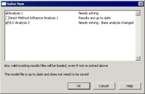 The
new multiple analyses facility also provides the means to
solve only selected analyses or loadcases for a model. For
models with more than one analysis the Solve now
toolbar button The
new multiple analyses facility also provides the means to
solve only selected analyses or loadcases for a model. For
models with more than one analysis the Solve now
toolbar button  displays a dialog showing the status of each analysis with a
check box showing whether an analysis needs to be solved (it
is checked) or not solved (it is unchecked).
A context menu for each analysis entry in
the Analyses  Treeview offers similar functionality, allowing individual
analyses to be solved in isolation from others (solving all
loadcases defined within that analysis), and a separate option
permits individual loadcases to be solved in isolation from
other loadcases defined within an analysis.
|
Cable tuning analysis for linear
structures
|
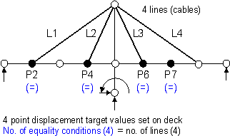 The
new cable tuning analysis facility calculates load factors for
selected lines in a model (that represent cables) in order to
achieve defined target values set for various feature types or
results components. It can be configured by selecting the Analyses
> Cable Tuning Analysis menu item. The
new cable tuning analysis facility calculates load factors for
selected lines in a model (that represent cables) in order to
achieve defined target values set for various feature types or
results components. It can be configured by selecting the Analyses
> Cable Tuning Analysis menu item.
By using the tabbed dialog presented,
lines in the model that represent cables are selected for
inclusion in the analysis, a solution method chosen, and model
or results loadcases specified to try and achieve target
values that are defined for particular components or features.
An 'exact' method, an optimisation facility and two best-fit
solution methods are provided.

|
Specify target criteria for linear
structures
The target values facility is a post-processing
tool that provides a general method of varying load factors in a
linear analysis to try and achieve target values defined for
particular feature types or results components. Target values can be
set by selecting the Analyses > Target Values menu
item. By using the tabbed dialog presented, a solution method is
chosen, and model or results loadcases specified to try and achieve
the target values defined. An 'exact' method, an optimisation facility
and two best-fit solution methods are provided. The target values
loadset created is similar to a combination, but the load factors are
automatically calculated by the program in response to the defined
targets.

Note that while cable tuning analysis is possible
using this target values method, it is simplified by using the new Cable
Tuning Analysis facility, which automates the definition and
assignment of the various loadcases required.
Direct Method influence analysis
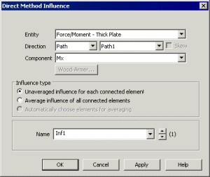
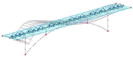
Direct Method influence analysis is a general and
powerful way of calculating influences for line beam, frame, grillage,
slab and deck models. It requires the definition of Direct
Method influence attributes. For each assigned attribute the
effect of a specified point load is assessed at each node or grid
location on a loadable area of a structure. The value of the load
effect of interest at each specified location is then used to
construct an influence line or surface for that location. Unlike the Reciprocal
Method (where influence types are limited to Shear, Moment,
Reaction and Displacement) the list of available results entity /
components available for influence calculation is only limited by the
elements used within the model. The Direct Method can calculate
influences for user-defined results components; for 3D beam models
including torsional effects; for slice resultants from shells;
calculate influence as a post-processing facility; and can calculate
influence for many locations and quantities with a single analysis.
|
|
|
|
Direct Method Influence
definition
|
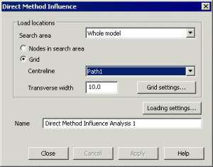
Direct Method Influence
assignment
|
|
|
|
|
|
|
|
|
The Analyses menu
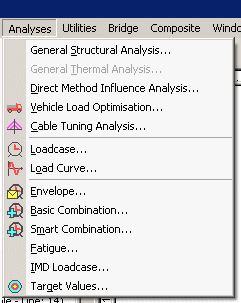 With
the ability to solve multiple analyses within one model in
Version 15.0 a new Analyses main menu has been added to
the Modeller user interface. It groups together the main
analysis types and loadcase-related entries. With
the ability to solve multiple analyses within one model in
Version 15.0 a new Analyses main menu has been added to
the Modeller user interface. It groups together the main
analysis types and loadcase-related entries.
Note that the analysis types that can be
accessed from the Analyses menu can also be accessed via
context menus for each analysis and loadcase entry in the
Analyses  Treeview (previously named as the Loadcases Treeview).
The new analysis options are described
individually on this New facilities and Improvements page.
|
Fast Parallel Solvers
A Fast Parallel Direct Solver and a Fast Parallel
Iterative Solver have been added to the existing range of solvers.
Both new solvers are high-performance, robust, memory efficient
solvers for solving large sparse symmetric and non-symmetric linear
systems of equations on shared memory multiprocessors.
Design code-related
improvements
Traffic Load Optimisation for beams
The use and assignment of direct
method influence attributes means that traffic load optimisation
for supported design codes can now be carried out for line beam
models. For a line beam model where the geometric section represents a
beam with a loadable top slab a loading grid of points can be used to
represent the slab. Influence shapes are created based upon the
loading grid points used and these, together with defining the extent
of the carriageway, allow Vehicle
Load Optimisation analysis to be carried out for line beams, just
as would be carried out for plate/shell models.
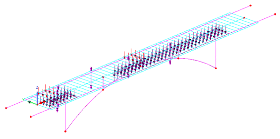
A new worked example is provided in the Application Example
Manual (Bridge, Civil & Structural).
LUSAS Traffic Load Optimisation for
Australia AS5100 and New Zealand SP/M/022 (2nd and 3rd Edition) codes
Road traffic loading to the Australia design code
AS5100-2:2400 and the Transit New Zealand Bridge Manual SP/M/022 is now supported by the LUSAS Traffic Load Optimisation
software as used in Vehicle Load Optimisation analysis. It has been
implemented with reference to:
- AS5100-2-2004 Australian
Standard, Bridge design, Part 2: Design loads.
- AS5100-7: 2004 Australian
Standard, Bridge design, Part 7: Rating of existing bridges
- Transit New Zealand Bridge Manual SP/M/022 2nd Edition (June 2003, with amendments June 2004, September 2004, and July 2005), and 3rd Edition (May 2013)
RC Slab Designer updated to support
new design codes
The RC Slab Designer can be used for
reinforced concrete slabs (without prestressing) that are modelled
using plate or shell elements.It enables plotting of contours and
values that indicate flexural reinforcement requirements at Ultimate
Limit State (ULS) or design crack width at Serviceability Limit State
(SLS) for those design codes that support this. The Codes of Practice
supported now include:
- AASHTO LRFD 5th edition (2010)
and AASHTO LRFD 6th edition (2012)
- AS5100-5-2004 Australian
Standard – Bridge Design - Part 5: Concrete and AS3600-2009
Australian Standard - Concrete Structures.
- British Standards BS5400-4
(bridges), BS8007 (Structures retaining aqueous liquids)
and BS8110 (buildings).
- CAN/CSA S6-06 - Canadian
Highway Bridge Design Code.
- Eurocode EN1992-1-1
(buildings): implemented for Austria, Belgium, Bulgaria, Cyprus,
Czech, Denmark, Finland, France, Germany, Greenland, Ireland,
Italy, Netherlands, Slovakia, Spain and United Kingdom.
- Eurocode EN1992-2
(bridges): implemented for Bulgaria, Cyprus, Denmark, Finland,
Ireland, Italy, Spain, Sweden and United Kingdom.
- IRC: 112-2011 - Indian
Highway Bridge Design Code.
- IRS: CBC-1997, IRS Concrete
Bridge Code 1997
- SS CP65: Part 1 and 2: 1999
– Singapore Code of Practice for Structural Use of Concrete and SS
EN1992-1-1 (Singapore National Annex to the Eurocode).
|
|
|
|
|
|
|
|
|
|
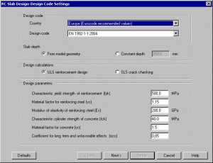
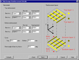
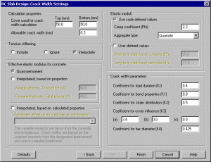
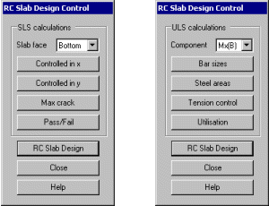
RC Slab designer dialogs and SLS and ULS design control
toolboxes
|
An updated worked example is provided in the Application Example
Manual (Bridge, Civil & Structural).
Exporting of data for use with
the Composite Deck Designer software option (PontiEC4)
The Composite
Deck Designer (PontiEC4) is a software option that enables comprehensive design checks to be made for
multiple sections along steel/composite bridge decks to Eurocode
EN1994. PontiEC4 carries out design calculations covering ULS bending,
stress, shear and interaction; SLS stress, web breathing and cracking
and fatigue checks for main members and connectors.
By using the Bridge>
PontiEC4> Export menu item LUSAS force and moment results
data for selected elements can be exported for use in use in the
Composite Deck Designer (PontiEC4).
See Software Option - Composite Deck Designer
for more details.
Prestress Wizards now support
AASHTO LRFD 5th Edition, 6th Edition and EN 1992-1-1:2004 Eurocode 2
The Single and Multi-tendon prestress wizards now support AASHTO
LRFD 5th Edition, AASHTO LRFD 6th Edition and EN 1992-1-1:2004
Eurocode 2.
Static vehicle loading
library extended
|
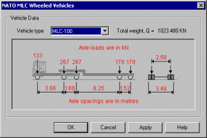
The following new static vehicle load
libraries can be accessed from the Bridge > Bridge
Loading menu:
 Australia
AS5100
Railway Loading 300LA, 300-A-12 and 300-A-12 (Single
Axle) Australia
AS5100
Railway Loading 300LA, 300-A-12 and 300-A-12 (Single
Axle)- Denmark
Special
vehicles defined as Load Model 3 (LM3) in the Danish
National Annex to EN1991-2
- Eurocode
Fatigue
Load Models 2, 3 and 4 in accordance with section 4.6
of EN1991-2
- Eurocode
High
Speed Train loading HSLM-A1 to A10 and HSLM-B loadings
- Finland
Special
vehicle loading as defined as Load Model 3 (LM3) in
the Finnish National Annex to EN1991-2
- NATO
Wheeled
and tracked vehicles
- Sweden
BRO Classification
Vehicles j-n added to existing library.
- UK
Special
vehicle types SV and SOV as defined as Load Model 3 in
the UK National Annex to EN 1991-2
- West Virginia
Truck
loads (Accessed from the United States of America
truck loading dialog)
|
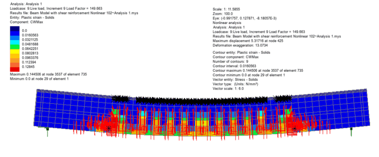
Crack width calculation to EN
1992-1-1
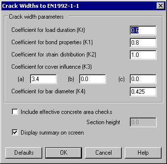
The Crack Width calculation facility is accessed using the
Bridge / Civil> Crack Widths to EN 1992-1-1 menu item. This is provided in selected Bridge and Civil
& Structural software products only. It enables plotting of contours of design crack widths in accordance with the EN 1992-1-1 design code. The calculations carried out are for reinforced concrete structures that are modelled using the Smoothed Multi Crack Concrete Model (Model 102), that have steel reinforcement modelled with reinforcement attributes, using a linear steel material model.
Bar
reinforcement attributes
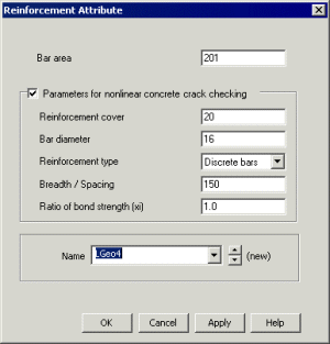
For use with the crack width calculation facility, reinforcement bar attributes are used to model the steel reinforcement in reinforced concrete. They can be defined by using the by
Attributes> Geometric> Bar reinforcement menu item. When used with the Smoothed Multi Crack Concrete Model (Model 102) and the Crack Widths calculation utility, contours and values of crack widths can be plotted in accordance with EN 1992-1-1:2004 Eurocode 2. Reinforcement attributes are similar to geometric line attributes but need to be assigned to lines meshed with bar elements for a chosen analysis to enable a crack width calculation to be carried out.
Bar attributes may be defined for a single reinforcing bar (Discrete bar method), as would be used in a 3D model, or be defined with suitable properties to represent a bundle or simplified arrangement of bars (Equivalent bar method) as would be used typically in a 2D plane strain analysis.
|
|
|
|
Crack widths to EN1992-1-1 dialog
|
Reinforcement attribute dialog
|
Results-related
improvements
Management of results files
In Version 15.0 the locations of all intermediate
and results files created during the building and solving of a model
can now be specified. These files can be located either within a
folder for each model, in the same folder as the model, or a specific
location dependent upon the model file location used.

Results files for models created prior to Version
15.0 will be listed in the Analyses  Treeview in sequence beneath the Analysis 1 entry. This effectively
provides the Version 14.7 working environment for old models within
the new multiple analysis capability of Version 15.0, but means that
the results files included in the Analyses
  Treeview can only be updated by opening and solving each relevant
model (as was the case in pre-Version 15.0 releases).
View Settings panel added to
Layers Treeview
|
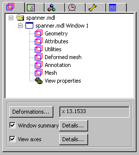 Deformations
(the amount by which the maximum deformation of a mesh shape
is scaled on screen) are now specified as part of the general
view properties for a particular model view window. Deformations
(the amount by which the maximum deformation of a mesh shape
is scaled on screen) are now specified as part of the general
view properties for a particular model view window.
As well as being added to the View
Properties dialog, a button to access the Deformations
settings has been added to a new 'Selected view settings'
panel at the bottom of the Layers  Treeview.
Window summary and View axes
check boxes, and Details... buttons have also been
added.
|
|
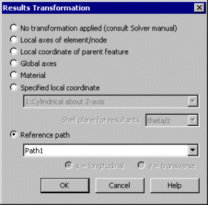 New
results transformation options New
results transformation options
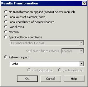
New results transformation options have been added for use
by all results and graphing dialogs that contain a Transformed
button.
The added options are:
- Local coordinate of
parent feature Transforms element results according to
the local axes of the line, surface or volume feature.
- Global axes
Transforms nodal or element results to the global axes.
- Reference path
Transforms nodal or element results relative to the angle
or route of a reference
path across or through a model..
Results transformation now stated on contour key
The type of results transformation
applied when creating a results plot is now written to the
Contour key.
|
Expandable basic
combinations
LUSAS assumes superposition is valid when
envelopes and combinations are assembled. In situations when
superposition may not hold true (as when lift-off supports are
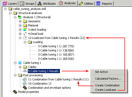
present) a nonlinear solution may be required. The factored loadcases
from a basic combination (as shown below for cable tuning results) may now be
created as a new loadcase from the basic combination definition
provided the basic combination does not include any smart combinations
or envelopes.

This is done by using the context menu for a combination,
or for the post- processing folder as shown below.
Plotting results for envelopes and
combinations
Top, middle and bottom results components and
principal and equivalent stresses can be now be selected as primary
components when plotting results for envelopes and combinations.
IMD Plus Peak Results and Group
Results
Enhancements to the user interface for the
IMDPlus software option allow the peak response to be obtained for a
selection of nodes or elements. Summaries are output that detail the
magnitude, time and location of the positive, negative and absolute
peak results for each component of a set of nodes or elements. These
results describe the overall behaviour of the structure and allow time
histories of locations that correspond to the reported peaks to be
specifically investigated. In addition, it is possible to calculate
node or element set quantities such as the sum and average of the
result time histories, together with their associated maxima and
minima.
Animations
- The resolution and aspect ratio of
an animation can now be set by specifying the number of pixels in
the horizontal and vertical directions. Initial default values are
related to the model view window size and are set to be either 800
pixels horizontally or 600 pixels vertically according the view
window aspect ratio.
- Once created, a new save button on
the animation dialog saves the animation as an AVI file and
automatically uses the Microsoft Video 1 compressor with 0.75
compression quality.
- When animating an active loadcase a
Ramp deformation function has been added to the existing Sine,
Square and Saw tooth options.
64-bit Solver results files
64-bit Solver results files can now be read in
the 32-bit version of LUSAS Modeller.
Plotting of crack width contours
and values
Crack width calculations and plotting of crack
width contours and values can now be carried out:
- For plane strain and solid models, when using the Smoothed Multi Crack Concrete Model (Model 102).
- For slabs, for design codes that support crack width calculation using the RC Slab Designer.
- In accordance with EN 1992-1-1:2004 Eurocode 2 when using the Crack Widths calculation utility with the Smoothed Multi Crack Concrete Model (Model 102).
Element-related changes
New 3D three-noded beam elements
A new group of 3D isoparametric thick beam
elements has been added to the element library. For use within
Modeller:
- BMI21 and BMI31 are straight and curved isoparametric degenerate
thick beam elements in 3D for which shearing deformations are included. The elements can accommodate varying geometric properties along their length. The elements may be used for linear and material nonlinear analysis of three dimensional beam, frame and arch structures, and can also be used to model cables in cable stayed structures. BMI21 may also be used as a stiffener for the QTS4 shell element; while BMI31 may be used as a stiffener for the QTS8 shell element. When Solver options 403 and 404 are turned on (as they are by default) the BMI21 element behaves the same as the 2-noded straight beam element BMS3 for linear analysis of structures containing straight members of constant cross-section. BMI21 is now the element selected by default when a 3D Thick Beam element is chosen on the line mesh dialog.
- BMX21 and BMX31 are straight and curved isoparametric degenerate thick beam elements in 3D for which shearing deformations are included. The element has a quadrilateral cross section which may vary along the element length.
New 2D axisymmetric two phase
elements
A new family of 2D axisymmetric solid two phase continuum elements
(TAX6P and QAX6P) has been added to join the existing 3D axisymmetric
solid two phase continuum elements used for drained and undrained soil
modelling.
Change to
thin beam elements
For thin beam elements section properties are no
longer input relative to the nodal line. Instead, and as always
defined for thick beams, section properties are now defined with
respect to a beam's neutral axis, and an eccentricity can be defined
when necessary.
New Material Models
Piecewise linear joint material
model
|
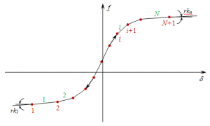 This
material model allows
a single force/displacement curve to be defined for each
freedom by defining a number of line (curve) segments This
material model allows
a single force/displacement curve to be defined for each
freedom by defining a number of line (curve) segments
|
Piecewise linear (Axial
force dependent) joint material model
|
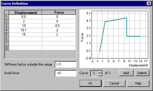 This
material model is similar to the generic piecewise linear joint
material model, but
allows any number of Force/Displacement curves to be
optionally specified by defining a number of curve segments
for a stated axial force. The joint is typically used for
modelling plastic hinges in pushover analysis. This
material model is similar to the generic piecewise linear joint
material model, but
allows any number of Force/Displacement curves to be
optionally specified by defining a number of curve segments
for a stated axial force. The joint is typically used for
modelling plastic hinges in pushover analysis.
|
Trilinear Earth Pressure joint
material
|
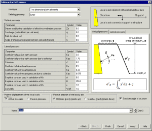 Tri-linear
(active/passive) earth pressure joint material simplifies the modelling of a
variety of soil-structure interaction problems. It creates a
piecewise linear joint material attribute with properties that
vary with depth representing soil layers. Earth pressures increase with depth along the vertical axis. Multiple attributes can be defined to represent layers of soil or changes in properties due to the presence of water. Tri-linear
(active/passive) earth pressure joint material simplifies the modelling of a
variety of soil-structure interaction problems. It creates a
piecewise linear joint material attribute with properties that
vary with depth representing soil layers. Earth pressures increase with depth along the vertical axis. Multiple attributes can be defined to represent layers of soil or changes in properties due to the presence of water.
Tri-linear earth pressure joint material is defined using the
Attributes> Material> Joint menu item. The input parameters and the number of degrees of freedom will vary according to the selected joint and model geometry.
A new
worked example provided in the Application Example Manual (Bridge,
Civil & Structural).
|
Modified Cam-clay material model
A modified Cam-clay material model has been added. The modified Cam-clay model is a
variant of the classic Cam-clay model used for the modelling of clays,
and is capable of modelling the strength and deformation trends of
clay realistically. The model can be used with standard continuum
elements as well as the two-phase elements which include the effects
of pore water pressure.
A new worked example is provided in the Application
Example Manual (Bridge, Civil & Structural).
Modified Mohr-Coulomb material
model
A modified Mohr-Coulomb material model has been
added to the material library. The modified Mohr-Coulomb model applies
a tensile and/or a compressive cut-off to the standard Mohr-Coulomb
model. When the standard Mohr-Coulomb model would potentially predict
tensile stresses beyond the uniaxial tensile limit of the material,
the tension cap may be used to prevent such stresses occurring. In compression the cut-off results in irreversible deformations once the maximum compressive stress is exceeded. The cut-off can be applied to either a single principal stress component or to the mean pressure.
Concrete creep and shrinkage
to Eurocode 2
Creep and shrinkage models as specified in Eurocode 2 have been
implemented in LUSAS. This material model can be used with beam
elements, 2/3D continuum elements, shell elements and continuum
composite elements.
New Smoothed Multi Crack
Concrete material model
The new Smoothed Multi Crack Concrete model
(Model 102) is similar to the Multi Crack Concrete model (Model 94),
but it converges more rapidly, is more robust and allows crack widths
to calculated and plotted for the Contours and Values layers as
component 'Plastic Strain'. As with Model 94, crack/crush results can
be plotted and planes representing the cracks can be displayed are
displayed in two and three-dimensions.
Piecewise linear bar material
model
|
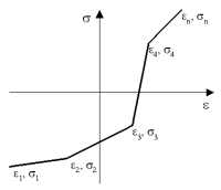 This
model provides a piecewise linear material for use with
2-noded bar elements to meet the requirements of no-tension
(compression-only) or no compression (tension-only) members.
The nonlinear elastic behaviour is recoverable, and during the
analysis the stiffness (and stress) will be computed from the
strain value using the relationship shown in the image below.
By defining curve data that runs along the positive (or
negative) strain axis, no tension (compression-only) or no
compression (tension-only) behaviour can be simulated. This
model provides a piecewise linear material for use with
2-noded bar elements to meet the requirements of no-tension
(compression-only) or no compression (tension-only) members.
The nonlinear elastic behaviour is recoverable, and during the
analysis the stiffness (and stress) will be computed from the
strain value using the relationship shown in the image below.
By defining curve data that runs along the positive (or
negative) strain axis, no tension (compression-only) or no
compression (tension-only) behaviour can be simulated.
|
Two-phase material enhanced
The Two-phase material model has been extended to
model partially saturated fluid flow through porous medium as, for
example, when investigating seepage of water through an earth dam,
where the position of the phreatic surface (the boundary between fully
saturated and partially saturated soil) is of interest.
Draining and filling curves can now be specified
for partially drained materials by defining the rate of water
extraction, weight factor, air entry and permeability values.
Manually-defined (piecewise linear ) draining and filling curves can
be defined for partially drained materials by specifying pore
pressure, relative permeability and effective saturation values.
Overall the coupled pore fluid diffusion/stress analysis capability
in LUSAS has been enhanced to:
- Establish the initial equilibrium state via a
geostatic analysis step.
- Model partially saturated fluid flow through porous
medium, e.g. seepage of water through an earth dam, where the
position of the phreatic surface (the boundary between fully
saturated and partially saturated soil) is of interest.
- Include the influence of the pore fluid weight on the
solid skeleton only (excess pore pressure solution) or on both the
solid skeleton and fluid (total pore pressure solution).
- Use a default analytical capillary pressure
relationship or define a piece-wise relationship in a tabular
form, as the accuracy of simulation depends on the use of an
accurate relationship.
- Specify different filling (or absorption) and draining
(or exsorption) capillary (or pore water) pressure – effective
saturation curves, which can exhibit hysteresis behaviour, as well
as a scanning curve for transition between absorption and
exsorption.
- In addition to prescribed head (pressure) and
impervious (closed) boundary conditions, inflow/outflow over a
boundary can be considered. It is also possible to control the
boundary condition automatically when a phreatic surface meets a
boundary surface using lift-off supports.
Geostatic control
A geostatic analysis control step has been
introduced to establish the initial equilibrium state in an analysis
involving a two-phase material.
Modelling-related
improvements
Lift-off / contacting supports
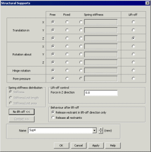
The existing structural support dialog has been
updated to allow lift-off and touchdown supports to be defined.
A lift-off support can be easily specified by
setting an appropriate lift-off control type, such as Force, Moment,
Hinge rotation, or Pore pressure, for a chosen degree of
freedom. Lift-off will take place once a stated value for that control
type has been exceeded. After lift-off has occurred the behaviour can
be set to release only the specified restraint, leaving all other
restraints applied, or release all restraints.
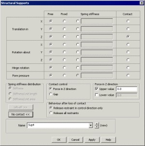
A contacting support can be specified by setting
the appropriate contact conditions such as either Force, Moment,
Hinge rotation, Pore pressure, or for a Gap.
Contact will be deemed to be taking place once a stated value has been
reached, or when the contact control type lies within a range of
specified values. After contact has occurred the behaviour can be set
to release only the specified restraint, leaving all other restraints
applied, or release all restraints.
|
|
|
|
Support dialog with Lift-off options
|
Support dialog with contact options
|
User-defined feature, node and element
numbering
|
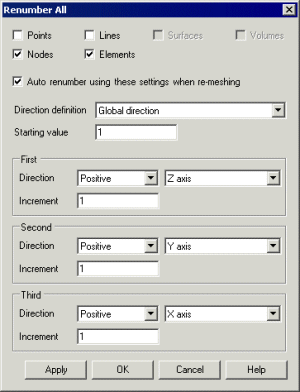 All,
or just selected Points, Lines, Surfaces, Volumes, Nodes and
Elements in a model can all be renumbered from a specified
starting value. Renumbering directions that dictate how the
renumbering facility will sweep or loop through the model can
be defined and be specified with reference to global axes or
reference paths. All,
or just selected Points, Lines, Surfaces, Volumes, Nodes and
Elements in a model can all be renumbered from a specified
starting value. Renumbering directions that dictate how the
renumbering facility will sweep or loop through the model can
be defined and be specified with reference to global axes or
reference paths.
|
Modelling units: input, conversion
and reporting
On dialogs with grid cells for dimensional input,
the units expected are now displayed as a tool tip when the cursor is
hovered over the input cell.
Units can be converted at the time of input on
all dialogs where dimensional input is expected by clicking inside the
right-hand edge of the edit box or grid cell and accessing the Units
Converter and Variation Utility. A range of conversion units are
supplied according to the type of input expected. Model units stated
are those previously set.
 |
|
Reporting of expected model
units and accessing the Units Convertor dialog
|
For edit boxes or grid cells that support
coordinate entry the conversion utility allows conversion of multiple
comma separated values in the one text box. So, for instance, a
coordinate entered as 100,200,300 would be converted to (0.1, 0.2,
0.3) if a millimetres to metres conversion was selected.
When Imperial modelling units have been set
coordinates and lengths can be input in feet and inches, instead of
just feet or just inches. For example, a distance of 5 feet, 11 ans a
half inches can now be input and
output as 5:11.5 (or more awkwardly as 5'11.5"), rather than either 71.5" or 5.92'.
Displaying and reporting of model and results
data (both to a View window and to print file output) is done in
accordance with the consistent set of units stated on the Model
Properties dialog. A new setting on this dialog provides an option for
Imperial modelling units to output coordinate and lengths in feet and
inches (e.g. 5'11.5") format.
Modelling units are now written to the Contour
key in the format "Component: Sx (units: N/mm2)", and
similarly into the window summary annotation for the diagrams, values
and contours layers.
Timescale units
Timescale units are now specified as part of the
creation of a new model and can be changed on the Model Properties
dialog. Choosing a timescale unit dictates how time-based values are
displayed on dialogs during modelling, and how they are output when
processing results. Setting a timescale unit does not change the
consistent set of model
units defined for a model, it simply permits the input or display
of chosen timescale units in a different unit of time to that defined
by the model units, wherever they are expected to be defined or
displayed/output.
Timescale units may be input in seconds, minutes,
hours or days. By default, seconds are initially selected to comply
with the consistent modelling units options provided.
Timescale units can also be converted at the time
of input on all dialogs where dimensional input is expected
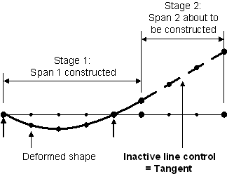
Improved Activation /
Deactivation of elements
|
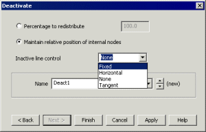 When
deactivating elements using the birth and death facility
options are now provided to maintain the relative position of
the internal nodes of a line beam to ensure they are
constrained and move as a rigid body. This prevents
incorrectly shaped deformed mesh plots that could be seen in
previous versions for particular modelling processes. An
inactive line control setting states how the deactivated
elements will be rotated or aligned with respect to existing
or previously activated adjoining lines in a model. When
deactivating elements using the birth and death facility
options are now provided to maintain the relative position of
the internal nodes of a line beam to ensure they are
constrained and move as a rigid body. This prevents
incorrectly shaped deformed mesh plots that could be seen in
previous versions for particular modelling processes. An
inactive line control setting states how the deactivated
elements will be rotated or aligned with respect to existing
or previously activated adjoining lines in a model.
|
|
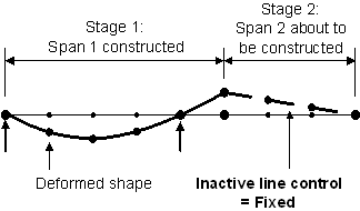
|
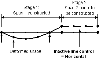
|
|
Fixed line control
|
Horizontal line control
|
|
|
|
|
|
Tangential line control
|
OpenGL speed-up
Version 15.0 improves the OpenGL graphics driver
for LUSAS:
- Changes made to the OpenGL
implementation have reduced a noticeable pause that was seen after
very large models had been rotated in the View window.
Section Library and Section
Property Calculator improvements and changes
|
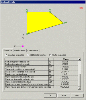 The
main section library and the user-defined section property
libraries, accessed via the Attributes > Geometric
Properties > Section Library menu item, have been
enhanced to include additional parameters (shear centres,
warping, radius of gyration, plastic properties) for use with
design calculations. The
main section library and the user-defined section property
libraries, accessed via the Attributes > Geometric
Properties > Section Library menu item, have been
enhanced to include additional parameters (shear centres,
warping, radius of gyration, plastic properties) for use with
design calculations.
The arbitrary section property calculator
accessed via the Utilities > Section Property
Calculator > Arbitrary Section menu item has also
been enhanced to calculate the same additional properties
(shear centres, warping, radius of gyration, plastic
properties) for use with design calculations.
Note that standard section property
calculators for standard sections (such as rectangular,
circular, L-sections, T-sections etc) and for box sections
(both simple and complex), accessed via the Utilities > Section
Property Calculator menu item, do not currently calculate
the additional section properties for use with design
calculations. Instead, after defining a section shape, a new
option to Create geometry should be used to draw the
section prior to using the arbitrary section property
calculator to calculate the full set of section properties for
the shape. Note that the additional properties required for
design calculations are not required for a general analysis to
be carried out.
|
Creation of holes in arbitrary sections
When creating 2D models
with holes for section property calculation purposes the Delete
geometry defining holes option no longer needs to be
de-selected prior to carrying out the section property calculation.
Instead, the properties of the surfaces representing holes are
automatically deducted from the overall section property calculation.
Additionally the previous requirement of grouping all holes together
into a group named Holes is no longer required where a single
surface contains one or more holes totally inside its boundaries, or
for when a hole exists between two surfaces.
Precast sections without a slab
|
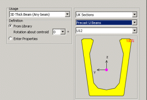 Precast
sections (without a slab) for EU, UK, USA, and Australia have
now been made available in the main section library so that
they can be used directly in stiffened plate models where the
slab is modelled with shell elements. These are accessed via
the Attributes > Geometric Properties > Section
Library menu item. Precast
sections (without a slab) for EU, UK, USA, and Australia have
now been made available in the main section library so that
they can be used directly in stiffened plate models where the
slab is modelled with shell elements. These are accessed via
the Attributes > Geometric Properties > Section
Library menu item.
The Utilities > Section
Property Calculator > Precast Section menu item now
only creates section properties (including those required for
design calculations) for sections with a slab.
|
Automatic computation of length of
section boundary for concrete creep and shrinkage analysis
For the CEB-FIP Model Code 1990 and the
EN1992-1-1:2004 concrete creep and shrinkage models, and for beams, the length of section boundary (the
nominal size) is now computed automatically for each element by LUSAS
and for tapered sections will vary along the beam. For voided
cross-sections a default internal perimeter factor of 0.5 is used, but
the means to specify a different internal perimeter factor is
provided. Outer and inner perimeters are calculated automatically by
the LUSAS section property generators.
Rationalisation of model
files on disk
In Version 15.0 the location of files that are created and saved in
the course of a building a model and running the various analyses that
may be associated with it can now be specified. For each model files
such as results files (.mys), solver output files (.out), solver data
files (.dat) may be saved:
- Within a folder for each
model, called "Associated Model Data"
- Within a folder with the
same name as the model
- Within the same folder as
the model (V14.7 behaviour)
- To a specified
(user-defined) folder
The Associated Model Data folder for a
model additionally contains two sub-folders called 'Backups' and
'Sessions'. A copy of the original model is preserved in the Backups
folder when the model is loaded for editing. The Backups folder can
contain any user-defined number of backup copies of a model. The
Sessions folder contains all session files (.ses) and model recovery
files (.rcv) for the model. This provides a more structured file
system and simplifies searching for, and opening, associated model
data on disk.
In addition to the Backups folder it is also
possible to maintain an additional copy of the model file in another
location. The Backups tab on the Modeller Properties dialog controls
where and how many backup versions (revisions) are saved.
Reference paths now more widely used
The use of reference paths has been extended
from their initial use (modelling of multiple varying sections) into
two new areas:
- They are used in the definition of a Direct Method
influence attribute (where for grillages they aid in the
calculation of influences for, and the identification of
longitudinal and transverse members), and also in the definition
of a loading grid that can be used as an alternative to using the
nodes or points present in the model for an influence analysis.
- The specification of a reference path provides an easy
way of transforming results relative to the angle or route of the
defined path.
|

|
|
|
Direct Method Influence definition using a reference path
|
Transformation of results to align to the angle or route of
a reference path
|
Prestress definition in 2D planes
The tendon profile and the multi-tendon profile
dialogs now permit defining a tendon profile in two 2D planes as well
as defining it in 3D space. This two 2D plane method is preferred
in certain countries, and requires tendon profile coordinates to be
defined in both ZX and XY planes. Projection and rotation angles can
additionally be defined to cope with inclined webs and rotated
sections.
Reporting of tendon setting-out
information
|
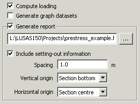 The
calculated tendon profile shape (after all smoothing has been
applied) can be included in a summary report in a format that
is suitable for setting-out the tendon on-site. Tendon profile
data can be tabulated for a defined spacing along a
beam and with reference to vertical origin and horizontal
origin. The origin settings can be set to be an assigned
line or the top or bottom, left or right, or centre of a
geometrically defined cross-section. Each tendon assignment
writes a separate setting-out chapter where the tendon profile
information is stated as relative distances between
setting-out points. The
calculated tendon profile shape (after all smoothing has been
applied) can be included in a summary report in a format that
is suitable for setting-out the tendon on-site. Tendon profile
data can be tabulated for a defined spacing along a
beam and with reference to vertical origin and horizontal
origin. The origin settings can be set to be an assigned
line or the top or bottom, left or right, or centre of a
geometrically defined cross-section. Each tendon assignment
writes a separate setting-out chapter where the tendon profile
information is stated as relative distances between
setting-out points.
|
Assigning an attribute to all
relevant features
A new context menu item Assign to all is
available for all attributes in the Attributes  Treeview. When chosen, the attribute is automatically assigned to all
relevant geometric features (or to mesh objects in a mesh-only model)
for a particular analysis and loadcase without those features having
to be selected prior to the assignment.
Assign to all is different in use from the
Set Default context menu item, which is also available for
attributes, in that when it is clicked the attribute is assigned to
all relevant features in the model regardless of whether they have
been assigned an attribute of the same type previously or not. The Set
Default menu item only applies the attribute to any features created
after the default was set.
Assigning a load attribute to
multiple loadcases
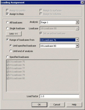 New options to enable assigning a load attribute to
All loadcases
or a Range of loadcases have been added to the loading assignment
dialog. New options to enable assigning a load attribute to
All loadcases
or a Range of loadcases have been added to the loading assignment
dialog.
Attribute/Utilities data transfer
between models
The library browser allows users to transfer
attribute data (such as mesh, geometric, material, loading, and
supports) and associated utilities and report data between models. It
is accessed using the File > Library menu item.
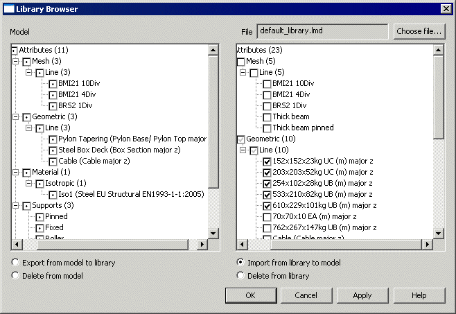
The library browser displays a list of the
attributes and utilities for the currently open model, alongside a
list of attributes and utilities that have been saved in the selected
LUSAS model data library file. Selected attribute data can be exported from a
model to the library, or imported to a model from the library. Checks
take place to ensure that data is not unknowingly overwritten.
Attributes can also be deleted from the mode,l or library, using this
facility.
The dialog below shows the selection of
five geometric line attributes in readiness for improting from the
library to the model. Checkboxes are disabled (as shown
by  ) according to whether import or export of data has been chosen. ) according to whether import or export of data has been chosen.
Defining Variations
 The
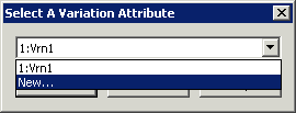
definition of variations (the means of varying attributes over
features) can now be done from inside all dialogs that support the use
of the variations facility by selecting the New... entry on the
drop-down list that is displayed. Currently this only applies to: The
definition of variations (the means of varying attributes over
features) can now be done from inside all dialogs that support the use
of the variations facility by selecting the New... entry on the
drop-down list that is displayed. Currently this only applies to:
- Defining variations in general
- Transformations - such as when assigning discrete
loads
- Local coordinates - such as when defining geometry
Mapping of Keyboard Modifiers for
Cursor and Area Selection
The Cursor drop-down menu contains a Keyboard Mapping...
menu item that allows the default Windows-based cursor and area
selection keyboard modifiers to be changed to user-defined shortcuts.
This feature makes the use of LUSAS Modeller more familiar to those
used to CAD modelling systems.
Cylindrical / Spherical Local
Coordinates
The definition of cylindrical and spherical
coordinates has been rationalised.
- A cylindrical coordinate system is
based on the axes of a cylinder defined by a radius, angle and
distance along the cylinder axis.
- A spherical coordinate system is
based on the axes of a sphere defined by a radius, tangential
angle and angle around a meridian.
Improvements to Prescribed Loading
Prior to Version 15 the assignment of a
prescribed displacement of zero to a freedom of a node (in order to
return it to an original undeformed position) also required the
assignment of a support in order for the displacement to be effective.
Now, in Version 15, the support need no longer be assigned by a user.
Instead Modeller creates a 'hidden' support that remains active in all
following loadcases, until it is superceded by either another
prescribed displacement load, or another support assigned to a
following loadcase. So a Prescribed Loading entry within an analysis
loadcase in the Attributes  Treeview
effectively represents a support condition. Treeview
effectively represents a support condition.
64-bit version of LUSAS
A 64-bit version of LUSAS Modeller and LUSAS
Solver is now available and this provided as an independent
installation file. The 64-bit version of LUSAS Modeller has no
geometry engine so only allows for assignments to be made to the mesh
(known within LUSAS as ‘mesh only modelling’) and results
processing. The 64-bit version of LUSAS Solver is functionally the
same as the 32-bit version. Results files from the 64-bit Solver can
be processed in either the 32-bit or the 64-bit version of LUSAS
Modeller.
In order to use the 64-bit versions a 64-bit
operating system must be installed.
General improvements
Automated error reporting
LUSAS Modeller makes use of a third party crash
reporting facility (CrashRpt) to allow users to optionally submit
crash reports to LUSAS for investigation. If a crash occurs a crash
dump is also assembled.
An option to Restart LUSAS Modeller after
submitting the error report is also provided. This enables a model
recovery to be carried out.
Other user change requests
In addition to the range of new facilities and
improvements listed, many user change requests have also been
implemented. The originators of all requested changes to the software
(some of which are included in the above list of enhancements) have
been incorporated in this release will be notified individually.
User Manuals
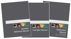
User manuals
All online and printed documentation has been
updated for this new release. Manuals are provided in PDF format as
part of any V15 software download file or on the V15 software CD.
 Worked Examples Worked Examples
All worked examples have been updated for this release
to ensure that the examples match changes made to the software and
(where possible) to illustrate new facilities.
- The Nonlinear Concrete beam
example has been moved from the Examples Manual to the Application
Examples M\anual (Bridge, Civil & Structural)
New Worked Examples
The following examples have been added to the Application
Examples Manual (Bridge, Civil & Structural) to illustrate new
facilities added in V15.0
- Cable tuning analysis of a
pedestrian bridge - showing the use of cable tuning with a
linear analysis.
- Vehicle load optimisation of a
box beam bridge - showing use of vehicle load optimisation
using Direct Method Influence attributes,
- Embedded retaining wall -
showing use of the new trilinear earth pressure material,
- Trapezoidal earth dam with a
drainage toe - showing use of two-phase material,
consolidation, pore pressure and seepage modelling and the use of
a geostatic step,
Manuals of Worked Examples are provided in PDF
format as part of the LUSAS software download file or release CD.
Potential issues
opening PDF files referenced in CHM files
On some PCs, and for
certain operating systems, the installation of security updates as
released by Microsoft can affect the opening of PDF files from the
table of contents panel within the CHM file-based help. Any links to
PDF files from within help topic pages may similarly be affected.
If problems are
found when attempting to open these files from within the online CHM
file supplied please note the following:
-
All manuals are
supplied in PDF format on the installation kit and these are
normally installed into the <LUSAS Installation Folder>
/Programs/PDF_Manuals folder.
-
Workarounds/solutions
may be provided by Microsoft during the availability and support
of this particular LUSAS software release.
-
LUSAS is looking
into producing online help in alternative formats.
Retired
elements, material models and facilities
|