User Area
Software Release History - Version 17
New Facilities and Improvements
in LUSAS Version 17.0-x
Release history
V17.0-6 made available on 13 January 2021
This is an error
fix release to correct an urgent software issue preventing the loading
of any results file generated since midnight 1st January 2021 into
LUSAS Modeller.
Other error fixes and
change requests are included.
V17.0-5 made available on 7 March 2019
This was an
error fix release for one change request
V17.0-4 made available on 11 January 2019
This was an
error fix release for one change request
V17.0-3 made available on 26 November 2018
This was an
error fix release for one change request
V17.0-2 made available on 6 November 2018
This was an
error fix release for various change requests
V17.0-1 made available on 25 September 2018
(restricted release)
This was a
restricted release for various change requests
V17.0-0 made available on 21 May 2018.
This was a major release
of new facilitites and various change requests
In Summary:
Version
17.0-0 of LUSAS sees steel frame design and vehicle load
optimisation capabilities extended, prestress enhancements, additional
creep and shrinkage models, and new facilities for soil-structure
interaction modelling. New attribute viewing and editing features
simplify the management and editing of assignments, improving general
usability and enabling faster editing.
- The
Steel Frame Design option now supports EN1993-2:2006 Eurocode 3:
Design of steel structures - Part 2: Steel Bridges. Steel frame
design to EN1993-1-1: 2005+A1:2014 has been enhanced to
include Class 4 sections and to support shear buckling of
I-sections. The implementation for AASHTO LRFD 7th Edition
has been updated to allow user-defined input of buckling
properties.
- Vehicle
load optimisation has been extended to include Finland's LO
24/2014 design code, Norway's NS-EN 1991-2.2003 NA 2010 +
NA-rundskriv 07-2015, and the UK's BD21/01 Annexes D and E.
- Prestress
modelling has been re-structured and sees the single tendon and
multiple tendon prestress wizards, which were used to generate
prestress loading, retired. Instead, a tendon loading attribute,
which references tendon profile and tendon property data, can be
directly assigned to selected line, surface or volume features in
a model, consistent with all other attribute assignments made
within LUSAS. New tendon loading assignment options state how the
tendon loading is to be applied and, for assignment to lines,
mapping and offset options can be used, as well as specifying in
which loadcase(s) the tendon loading should apply. Prestress
loading is now calculated as a function of solving a model.
Prestress data can now be included in a model report by adding a
prestress chapter. Graphs showing prestress losses in tendons are
now produced using the graph wizard. Editing of tendon loading,
property and profile data has been improved and can be done by
individual selection of one or more attributes, or by selection of
the parent folder containing a set of attributes.
- New
material models include Creep and shrinkage for AASHTO LRFD 7th
edition, IRC:112-2011, a Duncan-Chang soil material model, and a
joint material model that allows definition of symmetrical matrix
properties -useful for specifying a joint representing a pilecap
sitting on a group of piles in a global (3D) model.
- Initial
stresses in soil can now be calculated by providing Ko data for
the supported material models that are used in soil analyses.
Modelling of the variation of material properties at any location
in a model can now be achieved by defining a profile variation.
Typical uses include modelling of varying soil properties with
depth, as obtained by borehole data
- Beam
section property calculation has been refined to give more
accurate values. Section
property calculation of a range of riveted or welded section types
is now provided in Bridge and Civil & Structural software
products. Sections can be defined with reference to sections held
in the main section library or from user-defined values. Indian
and New Zealand steel sections have been added to the steel
section library.
- Target
values for stress and strain can now be stated such that a
specified value for a selected results component for a feature
will be obtained exactly when a solve has taken place. This
facility is primarily for use when a specified jacking force is
required to be applied to one end of a line representing a cable.
- Editing
of attribute assignments is simplified by the new Assignments
editor, which allows simultaneous viewing, editing and management
of any number of attribute assignments, and is of particular use
in editing tendon profile and property assignments. A new
Attributes editor similarly enables easier viewing and editing of
loading data for a range of structural load types, and is of
particular use when editing tendon loading values when carrying
out prestress modelling.
- For
selections made in the View window, the Properties dialog has been
replaced with a new Properties panel, which allows for changing
the properties of any number of concurrently selected
features/objects, and permits assigning or deassigning attributes
to and from those items. A new Hierarchy panel lists the higher
and lower order features/objects of the currently selected
geometry feature or mesh object.
New facilities and improvements in
more detail:
| Steel
design
Traffic Load Optimisation
Prestress
Material modelling
|
General
enhancements
Element library
- Updated to
reflect Modeller enhancements
Documentation
Updated worked examples
|
Steel design improvements
Steel
design to EN1993-2: 2006 Eurocode 3
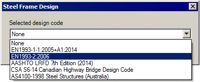 Steel
frame design now is now supported to EN1993-2: 2006 Eurocode 3: Design
of steel structures - Part 2: Steel Bridges. Eurocode National Annexes
currently supported are: Steel
frame design now is now supported to EN1993-2: 2006 Eurocode 3: Design
of steel structures - Part 2: Steel Bridges. Eurocode National Annexes
currently supported are:
- Eurocode
Recommended Values (EN 1993-2:2006)
- Finland
(SFS-EN 1993-2/NA:2010)
- Ireland
(I.S. EN 1993-2/NA:2010)
- United
Kingdom (BS EN 1993-2:2006/NA+A1:2012)
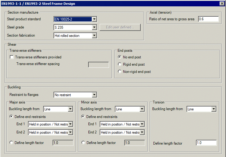 Steel
design to EN1993-1-1 Steel
design to EN1993-1-1
Steel frame design to
EN1993-1-1: 2005+A1:2014- EN 1993-1-1:2005 Eurocode 3: Design of
steel structures – Part 1-1: General rules and rules for buildings
has been enhanced.
- Class 4
sections are now supported.
- Shear
buckling of I-sections is now supported.
- The
reduced design plastic resistance moment allowing for shear force
as given by expression (6.30) of EN1993-1-1 for I-sections with
equal flanges has been extended to include class 3 sections.
Steel
design to AASHTO LFRD 7th edition
The Steel Frame Design attribute dialog
for the AASHTO LRFD 7th Edition code has been updated to separate
the input of buckling properties into those for compression buckling
and those for flexural buckling. As a result it is now possible to
specify a user-defined unbraced / buckling length for compression
buckling, and a user-defined unbraced length for flexural buckling.
LUSAS Traffic load optimisation improvements
Finland
LO 24/2014 added
When the country name 'Finland' and
Design Code 'LO 24/2014' is selected on the Vehicle Load Optimisation
dialog, traffic loading can now be generated according to Finland
standard:
- LO
24/2014 - Application of the Eurocode - Bridge loads and design
criteria - NCCI 1, Liikenneviraston (Finnish Transport Agency),
Helsinki.
Norway - NS
EN1991-2.2004 NA 2010 + NA-rundskriv 07-2015 added
When the country name 'Norway' and
Design Code 'EN1991-2 Norway 2010 + NA-rundskriv 07-2015' is selected
on the Vehicle Load Optimisation dialog, traffic loading can now be
generated according to the following:
- NS-EN
1991-2.2003 NA 2010 Eurokode 1: Laster på konstruksjoner - Del 2:
Trafikklast på bruer
- NS EN
1990-2002 A1 2005 NA 2016 Eurokode: Grunnlag for prosjektering av
konstruksjoner
- NA
Circular 07/2015 Traffic Load in manual N400 Bruprosjektering
State Highways Authority of Norway
United
Kingdom - BD 21/01 Annexes D and E added
When country name 'UK' and Design code
'BD21/01 Annexes D and E' is selected on the Vehicle Load
Optimisation dialog, main road traffic loading can now be generated
to:
- BD21/01
The Assessment Of Highway Bridges And Structures Design Manual for
Roads and Bridges, Volume 3, Section 4, Part 3, Highways Agency,
May 2001
Prestress improvements
Prestress
modelling restructured and easier to use
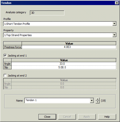
The single tendon and multiple tendon
prestress wizards that in previous versions were used to generate
prestress loading have been retired. Instead, a tendon loading attribute,
which references tendon profile and tendon property data, is defined
having a specified prestress force and associated jacking and loss
details. Once defined, this tendon loading attribute is added to the
Attributes  Treeview,
where it can be directly assigned to selected line, surface or volume
features in a model consistently with all other attribute assignments
made within LUSAS. Treeview,
where it can be directly assigned to selected line, surface or volume
features in a model consistently with all other attribute assignments
made within LUSAS.
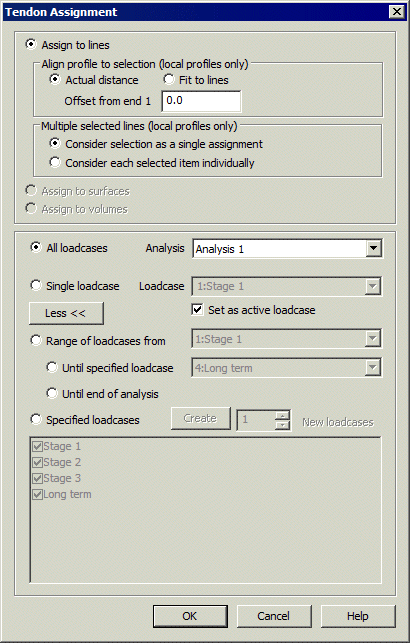
Tendon loading assignment options state
how the tendon loading is to be applied and, for assignment to lines,
mapping and offset options can be used, as well as specifying in which
loadcase(s) the tendon loading should apply.
 |
 |
| Tendon
loading attribute dialog |
Tendon loading attribute
assignment dialog
|
- Prestress loading is now calculated
as a part of solving a model. When solved, LUSAS still calculates
equivalent nodal loading from the assigned prestress tendon loads
and assigns these forces automatically to selected features
(and hence nodes and elements) of the model for a specified
loadcase. The discrete loads and the applied forces / moments
calculated are not created as attributes in the treeview but can
be reproduced / viewed for checking purposes.
- The properties, profile, loading,
losses and setting-out data for all tendons defined and assigned
in a model can now be reported upon by adding a prestress chapter
to a model report.
- Graphs showing prestress losses in
tendons are now produced using the graph wizard.
- Editing of tendon loading, property
and profile data has been improved and can be done by individual
selection of one or more attributes, or by selection of the parent
folder containing a set of attributes.
- Prestress loading and editing is
further enhanced by general viewing and editing enhancements made.
When opening pre-version 17 models
containing single and multiple tendon generated tendon data note that:
- Single
tendon prestress wizard generated data is not converted
automatically to the latest tendon modelling data structures.
Tendon properties, profiles and discrete load data generated by
the wizard is retained.
- Multiple
tendon prestress wizard generated data is converted automatically
to the latest tendon modelling data structures, with tendon
properties, profiles and loadings all being updated and assigned
to the correct features. Discrete load and search area data
attributes that previously revealed the underlying implementation
no longer appear in the Attributes
 Treeview. However, once the model is solved the discrete load data
calculated can be viewed as described previously.
Prestress
loading now supported by plain stress, plane strain, shell and solid
elements
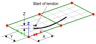 The
prestress loading capability has been extended to allow assignment to
surfaces modelled with plane stress, plane strain and shell elements,
and volumes modelled with solid elements. The
prestress loading capability has been extended to allow assignment to
surfaces modelled with plane stress, plane strain and shell elements,
and volumes modelled with solid elements.
Assignment of tendon loads to a surface
or volume modelled with these elements requires a tendon profile to be
defined using 'Global coordinates' on the Tendon Profile dialog.
The defined tendon length is used and
the tendon is positioned in the model at the start coordinate
specified within the tendon profile dataset.
Material models
AASHTO
LRFD 7th edition creep and shrinkage material model added
The AASHTO LRFD 7th edition creep and
shrinkage model can be used with beam elements, 2D/3D continuum
elements, semi-loof and thick shells, and composite solid elements.
AASHTO creep and shrinkage is only strictly applicable to beams,
however, in LUSAS the creep equations have been extended to 2D and 3D
stress states. The assumptions made in the derivation of this
extension can be found in the LUSAS Theory Manual.
- Creep
loss can be calculated with reference to either article 5.4.2.3.2
or the commentary clause C5.4.2.3.2-2.
- Shrinkage
loss can be calculated with reference to equation 5.4.2.3.2-2 or
the commentary clause C5.4.2.3.2-2
IRC112-2011
creep and shrinkage material model added
The IRC:112-2011 creep and shrinkage
model can be used with beam elements, 2/3D continuum elements,
semi-loof and thick shells, and composite solid elements. IRC:112-2011
creep and shrinkage is only strictly applicable to beams, however, in
LUSAS the creep equations have been extended to 2D and 3D stress
states. The assumptions made in the derivation of this extension can
be found in the LUSAS Theory Manual.
- Creep
calculations are carried out to IRC:112-2011 clause 6.4.2.7 and
Annexure A2, but elevated or reduced temperatures during curing
are not considered.
- Shrinkage
effects can be included in accordance with clause 6.4.2.6 and
Annexure A2 clause A2.6.
Duncan-Chang
soil material model added
The Duncan-Chang soil material model is
a simple model whose parameters are calculated by curve fitting
triaxial test data over a range of cell pressures. It takes an
incremental elastic approach in which Young’s modulus and
Poisson’s ratio are evaluated from current stresses. A predictor
step is used to determine whether the soil is loading or unloading,
following which, corresponding values of Young’s modulus and
Poisson’s ratio are calculated for use in the incremental elastic
modulus matrix.
The model can be used with standard
continuum elements as well as the two-phase elements. The modelling
parameters required can be evaluated in standard laboratory tests.
Matrix
properties for joint elements
The definition of symmetrical matrix
properties (stiffness, mass or damping) to specify a joint
representing a pilecap sitting on a group of piles in a global (3D)
model is now supported. This is achieved by selecting the Attributes
> Material > Joint menu item and choosing the Matrix
properties option.
|

|
|
Data
entry for a symmetrical matrix
|
Initialisation
of ground conditions (K0)
K0
data can now be defined for material models used in soil analyses,
principally, elastic models, Modified Mohr-Coulomb, Duncan-Chang and
Modified Cam-clay. Both the Duncan-Chang and Modified Cam-clay models
need the definition of an initial stress state to calculate an initial
stiffness.
The initial stresses in the soil can be
calculated by providing K0
data. On element activation, the effective vertical stresses in the
soil are calculated from the soil weight and any additional loads such
as overburden. Horizontal stresses are then calculated using the K0
value.
Profile
variations
Modelling of the variation of material
properties at any location in a model can now be achieved by defining
a profile variation. These are defined by selecting the Utilities
> Variation menu item. A typical use is modelling the
variation of soil properties with depth, as obtained by borehole data.
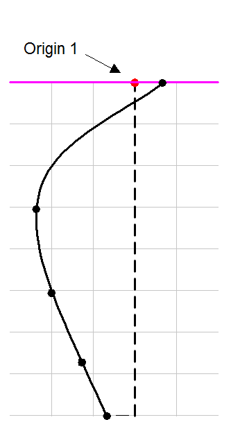
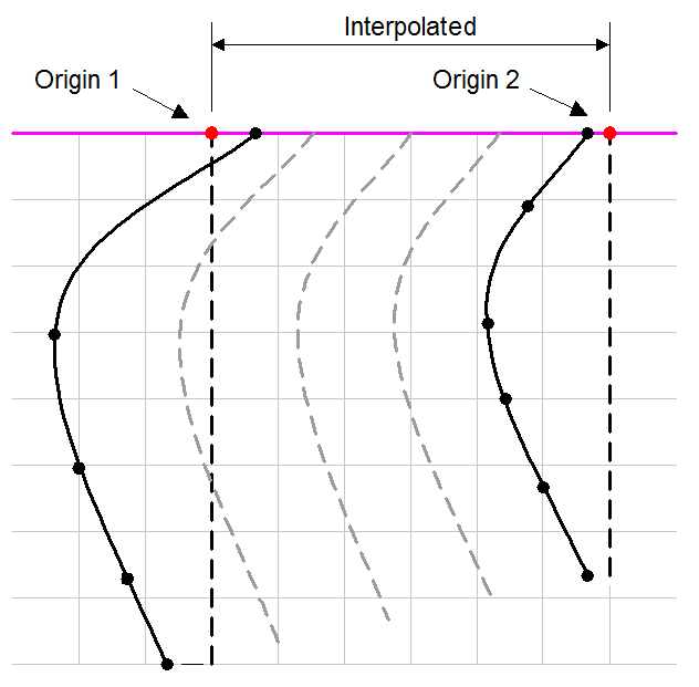
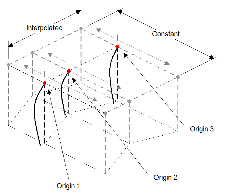
A single profile variation is defined
by sets of values against distance, but any number of profile lines
in-plane or out-of-plane may be grouped to form a profile set
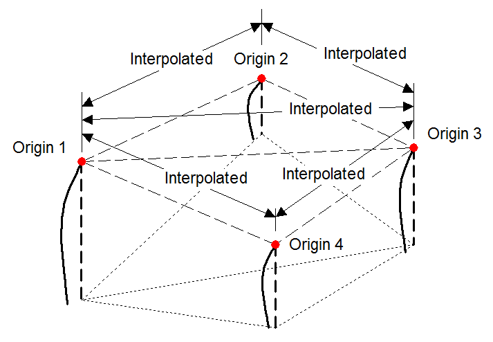
variation. When used to define particular material
properties in a supported material model, material properties for
elements in any region of a model are calculated by LUSAS Modeller by
interpolating between the distance and values defined for each element
between each profile variation location. The following images show how
properties are calculated with respect to the profile variation types
shown.
 |
 |
Single
profile variation
(Variation with depth only)
|
In-plane
set of two (or more) profile variations
(Variation with depth interpolated in-plane only)
|
 |
 |
In-plane
set of profile variations in a 3D model
(Variation with depth is only interpolated in the plane of the
profile set)
|
Out-of-plane
set of profile variations in a 3D model
(Variation with depth is interpolated in 3 dimensions)
|
General enhancements
Beam
section property calculation refined
Beam section properties for beams
listed in the section library are now computed using a more refined
calculation method. As a result, beam section property values are more
accurate, but differ slightly from those obtained in LUSAS version 16.
Section
property calculation of plated sections
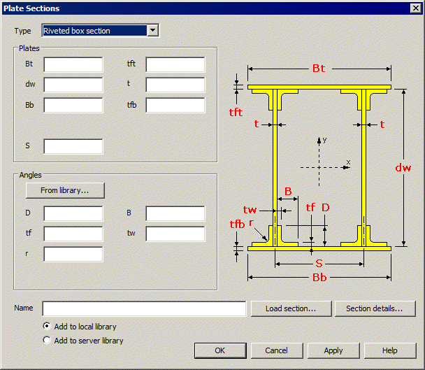 The
Plate Section Property Calculator is provided in Bridge and Civil
& Structural software products only and is accessed from the Tools>
Section Property Calculator > Plate Sections... menu item.
It allows definition of section geometry for a range of riveted or
welded section types, either with reference to sections held in the
main section library or from user-defined values, for saving into a
section library. The
Plate Section Property Calculator is provided in Bridge and Civil
& Structural software products only and is accessed from the Tools>
Section Property Calculator > Plate Sections... menu item.
It allows definition of section geometry for a range of riveted or
welded section types, either with reference to sections held in the
main section library or from user-defined values, for saving into a
section library.
Section types available:
- Riveted I section
- Riveted box section
- Riveted trough
- Riveted box from I
sections
- I section with channel
- Riveted box from
channels (back to back)
- Riveted box from
channels (face to face)
- I section with doubler
plates
- Welded plate box
- Riveted T section
- Riveted cruciform
Indian steel
section library added
Section properties for a range of
Indian steel sections have been added. The following are supported:
- Junior beams
- Light weight Beams
- Wide flange beams
- Heavy weight beams
- Junior channels
- Light weight channels
- Square hollow sections
- Rectangular hollow
sections
New Zealand steel
section library added
Section properties for a range of New
Zealand steel sections have been added. The following are supported:
- Universal
Beams
- Universal
Columns
- Universal
Bearing Piles
- Taper
Flange Beams
- Parallel
Flange Beams
- Equal
Angles
- Unequal
Angles
- Welded
Beams
- Welded
Columns
- Circular
Hollow Sections
- Square
Hollow Sections
- Rectangular
Hollow Sections
Australian
taper flange beam properties updated
The section properties for 125TFB and
100TFB have been updated.
Stress
and strain target values (for cables)
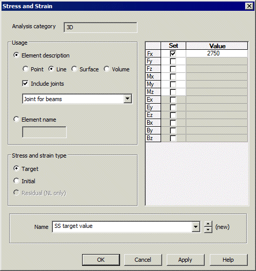 Stress
and Strain loading has been enhanced to include a Target
option. This is used to define a value for a selected results
component for a feature that will be obtained exactly when a solve has
taken place. Stress
and Strain loading has been enhanced to include a Target
option. This is used to define a value for a selected results
component for a feature that will be obtained exactly when a solve has
taken place.
This facility is primarily for use when
a specified jacking force is required to be applied to one end of a
line representing a cable. Note that target values are only
appropriate for linear materials.
Improved
viewing and editing of attribute assignments
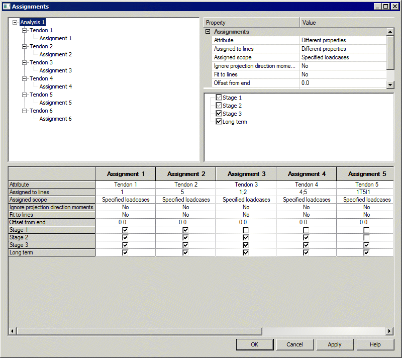
The new Assignments editor is displayed
when one or more attributes of the same type are selected for editing
in the Attributes  Treeview by using the View Assignments context menu item. The
editor can also be accessed from any assignments that exist in the
loadcases panel of the Analyses
  Treeview. It allows simultaneous viewing, editing and management of
any number of attribute assignments. Editing of data can be by
individual selection, or by selection of the parent folder containing
a set of attributes. The dialog is expandable.
Improved
viewing and editing of multiple load attributes
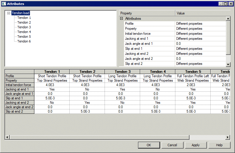
The new Attributes editor is presented
for particular structural loading attributes, when two or more of the
same loading type is selected for editing in the Attributes  Treeview by using the Edit context menu item. This can be by
individual selection, or by selection of the parent folder containing
them (providing no other different load types are present in that
folder). The dialog enables easy editing of loading data for a range
of structural load types, and is of particular use when editing tendon
loading values when carrying out prestress modelling.
Discrete
load projection over area for shell models
A new option 'Project over area (shell
models)' has been added to the discrete loading assignment dialog.
With this option, the offset distance from the load definition
position to the load position in the search area is used to calculate
a moment when the loading is assigned to shell elements.
New
Properties panel
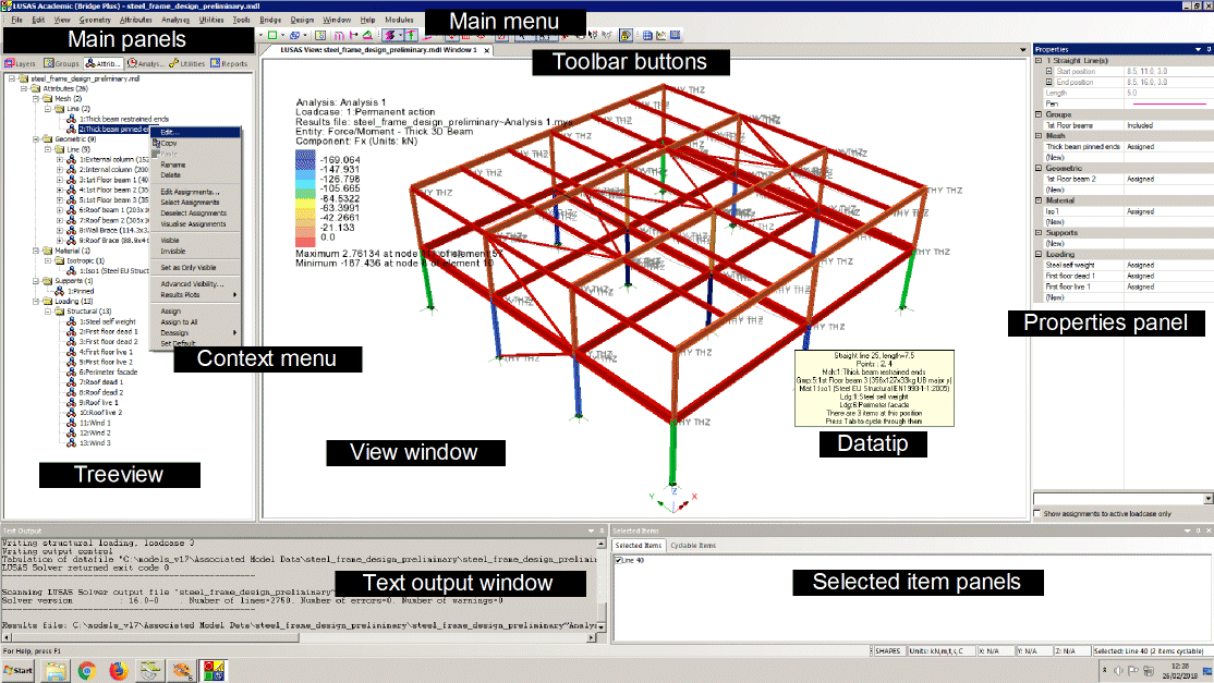
The Properties panel displays the
current properties of any number of selected geometry features
(points, lines, surface, volumes) and selected mesh objects
(nodes, edges, elements, faces) and displays the attributes which are
assigned to those selected items. It allows for changing the
properties of selected features/objects and for assigning or
deassigning attributes to and from those items. Unlike the Properties
dialog that it replaces, the new facility allows modification of any
number of features at the same time.
New
Hierarchy panel
The Hierarchy panel lists the higher
and lower order features/objects of the currently selected single
geometry feature or mesh object. Selection of a feature within the
hierarchy panel will update the panel to show the hierarchy for that
feature.
Changes
to the Element Library
No new elements have been introduced in
this release.
The capabilities of particular elements
have been enhanced to reflect relevant enhancements described
elsewhere for this release. For example, certain elements now support
additional creep and shrinkage codes.
User
change requests
In addition to the range of new
facilities and improvements listed, many user change requests have
also been implemented. The originators of all requested changes to the
software (some of which are included in the above list of
enhancements) that have been incorporated in this release will be
notified individually.
Documentation
User manuals
All online and printed documentation
has been updated for this new release. Manuals are provided in PDF
format as part of any Version 16 installation, and are also available
for download from the LUSAS website.
Updated
Worked Examples
The following examples have been
updated to show the use of selected new facilities added in this
release.
- Linear
analysis of a post tensioned bridge - Updated to show the use
of the restructured prestress modelling facilities.
- Segmental
construction of a post tensioned bridge - Updated to show the
use of the restructured prestress modelling facilities.
- Drained nonlinear
analysis of a retaining wall - Updated to show use of profile
variations and initialisation of soils using Ko.
All other examples have been updated to
ensure that the examples match changes made to the software.
Individual worked examples in PDF
format are provided as part of the LUSAS software download file or
release DVD, as well as being available from the LUSAS User Area.
Other
Potential
issues opening PDF files referenced in CHM files
On some PCs, and for certain operating
systems, the installation of security updates as released by Microsoft
can affect the opening of PDF files from the table of contents panel
within the CHM file-based help. Any links to PDF files from within
help topic pages may similarly be affected.
If problems are found when attempting
to open these files from within the online CHM file supplied please
note the following:
- Selected
manuals are supplied in PDF format on the installation kit and
these are normally installed into the <LUSAS Installation
Folder>/Programs/PDF_Manuals folder.
- Workarounds/solutions
may be provided by Microsoft during the availability and support
of this particular LUSAS software release.
Previous new facilities and improvements in
this release
None, this is the first release of
Version 17.
|