LUSAS New Release and Software Feature Videos
Watch a short video to find out about
new software releases and see
specific features of LUSAS in action.
See also:
 LUSAS
conference papers and presentations LUSAS
conference papers and presentations
LUSAS
webinar recordings
LUSAS Version 24.0
LUSAS Version 23.0
LUSAS Version 22.0
LUSAS Version 21.1 and 21.0
|
|
|
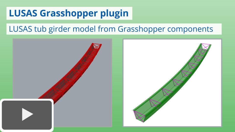
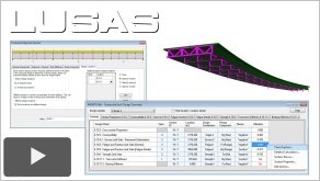
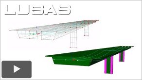
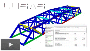
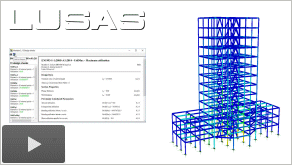
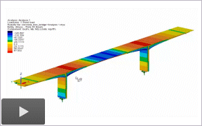
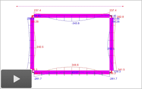
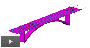
 LUSAS
tub girder model created from the LUSAS Grasshopper plugin
(2:39)
LUSAS
tub girder model created from the LUSAS Grasshopper plugin
(2:39)
|
|
|
|
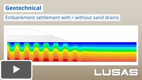
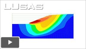
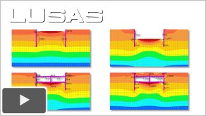
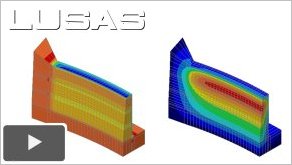
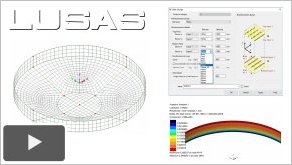
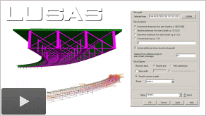
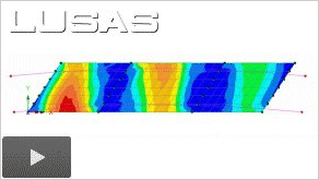
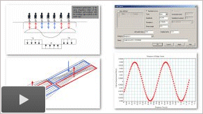
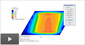
Embankment
settlement with / without the use of sand drains (4:11)
|
|
|
|
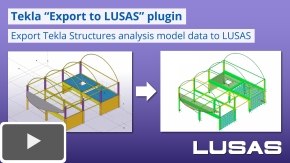
Tekla
"Export to LUSAS" plugin (2:33)
-
Export Tekla
Structures analytical model data
for use with LUSAS in order to solve a linear static
analysis and optionally extend the model to carry out
design checks or to include loading, dynamics, nonlinear
or other advanced options. (Version 21)
|
|
|
|
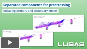
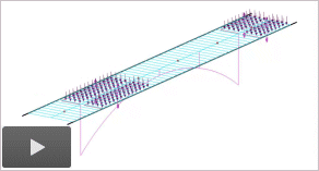
Separated
components for prestressing (3:44)
-
Watch
how, for beam models, it is
now possible to calculate and view, for each stage of
construction, primary and secondary load effects arising
from prestressing, and primary effects from each tendon
loss type (friction, anchorage, elastic shortening,
creep, shrinkage and relaxation).
(Version 21.1)
|
|
|
|
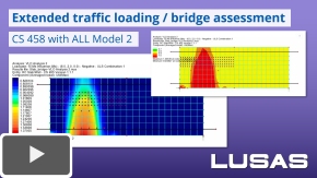
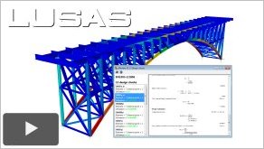
Enhanced
traffic loading and bridge assessment (1:37)
|
|
|
|
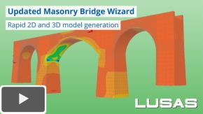
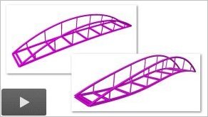
Updated
Masonry Bridge Wizard (5:19)
|
|
|

|
LUSAS
Version 21 Overview Presentation (7:57)
|
|
|
|
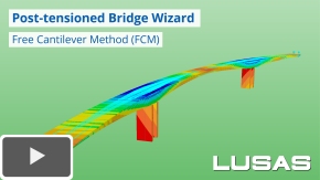
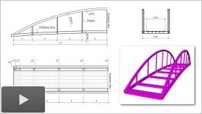
Post-tensioned Bridge
Wizard (10:00)
|
|
|
|
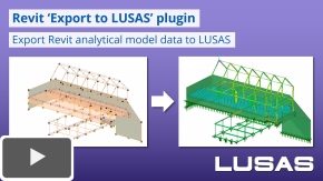
Revit
"Export to LUSAS" plugin (2:08)
|
|
|
|
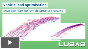
Vehicle load
optimisation using Envelope Runs (4:33)
|
|
|
|
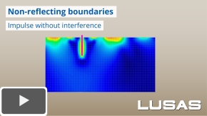
Non-reflecting
boundaries (3:22)
|
|
|
|
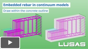
Embedded rebar in
continuum models (3:56)
-
Model reinforcement bar
arrangements in 2D and 3D continuum models or import
from Revit or other CAD software. (Version 21)
|
|
|
|
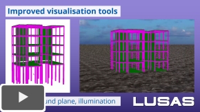
Improved
visualisation tools (1:09)
|
|
|
|
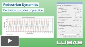
Pedestrian dynamics
(8:41)
-
Easily
define excitations for a single pedestrian, groups of
walkers or joggers, to suit international codes of
practice and generate a transient analysis with the
appropriate moving and varying loads. (Version 21).
|
|
|
|
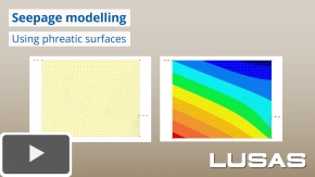
Seepage modelling
using phreatic surfaces (1:35)
|
LUSAS Version 20
LUSAS Version 19 and 19.1
|
|
|
LUSAS
Version 19 (1:00)
|
|
|

|
LUSAS
Version 19 Overview Presentation - More Productivity
(10:02)
|
|
|
|
LUSAS
Version 19 Overview Presentation - More Design
(7:57)
|
|
|

|
LUSAS
Version 19 Overview Presentation - More Applications
(6:10)
|
|
|
|
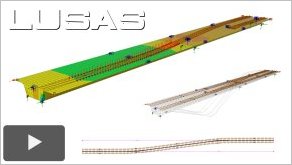
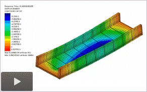
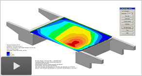
Steel Composite
Bridge Wizard (10:23)
-
Watch
how to create a beam and shell model of a 3-span curved
steel composite bridge using the Steel Composite Bridge
Wizard. Composite sections, girders, spans,
supports are defined prior to generating an initial
bridge model from the input data. Stiffeners and
cross-bracing details are added also using the wizard
and the bridge is re-generated to show their inclusion
in the model. After solving the model, bending moment
results are displayed for a selected girder by using the
slice resultants facility. (Version 19.0)
|
|
|
|
Composite Bridge Deck
Design (6:54)
|
|
|
|
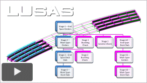
Branched
analysis for staged construction checks (5:07)
-
Watch how to
use the branched analysis facility to set-up and carry
out buckling, stability and other what-if checks for chosen
construction stages, or to consider an alternative
construction sequence. (Version 19.0)
|
|
|
|
Phi-C reduction soil
stability checks (1:44)
|
|
|
|
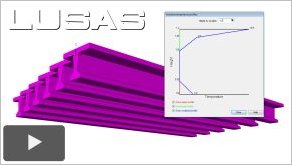
Temperature
profile loading (1:25)
-
Watch how to
model temperature profile loading of a concrete deck
with a slab and surfacing to Eurocodes. From defined
values the temperature loading is visualised over the
height of the deck and assigned to the model.
Temperature profile loading to other codes is also
available, as is manual definition of profiles.(Version
19.0)
|
|
|
|
Influence
analysis and enhanced
vehicle load optimisation (7:09)
-
Explains key
aspects of influence analysis and shows how influence
analysis can now also be carried at beam/shell slice resultant
locations. Influence results for selected locations on
the structure are viewed using contour plots, and then
used in a vehicle load optimisation analysis to derive
corresponding traffic loading positions on the bridge
deck. (Version 19.0)
|
|
|
|
CS
458 and AASHTO MBE loading (5:44)
|
|
|
|
Grillage modelling
(5:44)
|
|
|
|
Defining
member reinforcement and RC design checks to AS 5100
(7:06)
-
Shows how to
define reinforcement bar arrangements for member sections in a bridge model. RC design
attributes are specified and design checks carried out
on the bridge model showing the range of concrete design
checks and summary, detailed and interaction diagram
results that can be obtained.(Version 19.0)
|
|
|
|
Cut
and cover tunnel modelling (8:58)
-
Shows how activation
and deactivation of elements is used to model the
staged construction process of excavating the soil,
installing ground anchors and constructing the tunnel
structure. A linear and a nonlinear analysis is
performed to evaluate using different soil properties,
and a soil stability check is carried out using the
Phi-c reduction method. Live loading to simulate
vehicles passing over the ground above the tunnel is
applied prior to looking at bending moments in the
structural elements. (Version 19.0)
|
|
|
|
Simple
post-tensioned bridge - Part 1 (deck modelling) (8:32)
-
Shows the
import and building of a model of a 3-span slab bridge
with twin deep ribs, using beam and shell elements.
Constraint equations are used to tie the surfaces and
beams together to ensure composite action. Concrete
material, supports and gravity are assigned prior to
solving the model. The beam/shell slice resultants
facility is then used to view composite bending moments
along the deck. (Version 19.0)
|
|
|
|
Simple
post-tensioned bridge - Part 2 (prestress loading)
(8:26)
-
Shows the
addition of prestress loading to the bridge deck
modelled in Part 1. Tendon profiles are defined and
assigned to the model, requiring specification of tendon
properties, prestress force and jacking details, and
selection of the lines of the model to which they apply.
Concrete with creep properties and age assignments are
made prior to solving. The deformed shape from
self-weight and prestress loading is viewed for each in
isolation, prior to looking at the effects of both for a
long term loadcase. (Version 19.0)
|
|
LUSAS Version 18
|
|

|
LUSAS
Version 18 Update Presentation (10:43)
|
|
|
|
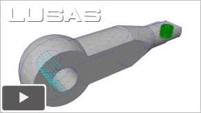
CAD import
and solid modelling of a cable connector (4:58)
-
Shows
third-party file types supported, then imports an IGES
file to create the basic geometry of a cable connector.
A solid model is defined and meshed showing the difference in
using linear and quadratic elements. Supports and
loading are added to represent in-service use, and once
solved, Von-Mises stresses are obtained
and additionally plotted on slice sections taken through
the connector. (Version 18.1)
|
|
|
|
Hygro-thermal
modelling of a concrete dam (10:50)
|
|
|
|
Vehicle
load optimisation to UK bridge assessment code CS 454 (4:10)
-
Shows how to
carry out a vehicle load optimisation analysis on a
three-span flat slab bridge modelled using shell
elements. Locations of interest are identified, and an
influence analysis run to calculate vehicle loading
patterns for maximum and minimum effects at the chosen locations. (Version 18.1)
For more
information see Vehicle
Load Optimisation
|
|
|
|
Train/rail
load optimisation (8:23)
-
Shows how to
carry out train/rail load optimisation analysis on a
two-span box beam bridge modelled using shell
elements. Tracks, including a crossover and a signal
stop location, are defined and visualised, and after
running an influence analysis, critical rail loading
patterns for a chosen design code are obtained for
selected track arrangements. (Version 18.0)
For more
information see Vehicle
Load Optimisation
|
|
|
|
Defining
member reinforcement and carrying out RC design checks
(14:03)
-
Shows how to
define reinforcement bar arrangements for beam and
column members in a simple building frame model, and
then how more complex section
reinforcement details are defined for arbitrary and
tapering sections in a bridge model. RC design
attributes are specified and design checks carried out
on the bridge model showing the range of concrete design
checks and summary, detailed and interaction diagram
results that can be obtained.(Version 18.0)
For more
information see RC
Frame Design.
|
|
|
|
RC
design checking of a circular tank wall (9:36)
|
|
LUSAS Version 17
|
|
|

|
LUSAS
Version 17 Update Presentation (7:32)
-
Version 17.0
sees steel frame design checking and vehicle load
optimisation capabilities extended to include EN1993-2: 2006 Eurocode
3, prestress
enhancements, additional creep and shrinkage models, and
new facilities for soil-structure interaction modelling.
New viewing and editing features simplify the management
and changing of attribute assignments, improving general
ease-of-use. Watch this short overview presentation to
find out more. (Version 17.0)
|
|
|
|
Steel
bridge design
to EN1993-2 Eurocode 3 (6:05)
-
Design checks for a steel railway bridge are carried out to EN1993-2: 2006 Eurocode 3: Design of steel structures - Part 2: Steel Bridges. Shows viewing of utilisation factors, and creation of a member report for a selected member to demonstrate the transparent nature of the LUSAS steel design checking facility, that shows the calculations made, revealing every step, every clause reference, and every
formula. (Version 17.0)
For more
information see Steel
Frame Design.
|
|
|
|
Post-tensioning in shell models (5:10)
|
|
|
|
Easier
viewing and editing of
attribute assignments (4:18)
-
Shows how to use the new loading attributes editor and the new attributes assignment dialog to make individual changes for multiple
selections. An incorrectly entered tendon force for a post-tensioned model is shown to be easily spotted and corrected. Then, by copying and pasting dynamic load factors from a spreadsheet to replace constant values used by a moving load, it is shown that the dynamic effect of a tank crossing a structure can be modelled. (Version 17.0)
|
|
LUSAS Version 16
|
|

|
LUSAS
Version 16 Update Presentation (13:48)
-
Version 16
marks a new era for LUSAS with the addition of comprehensive design checking tools for steelwork, and a host of other new features and enhancements that improve general usability and make collaboration between design teams easier.
Watch this short
introductory presentation video to find out more. (Version
16.0)
|
|
|
Steel
bridge design to AASHTO LRFD 7th Edition (7:29)
-
Design code-based combinations are created followed by steel frame design attributes that specify member design values, members lengths and end conditions used in the determination of buckling capacities. Design checks are carried out to AASHTO LRFD 7th edition showing utilisation factors, and a member report is created for a selected member to demonstrate the transparent nature of the LUSAS steel design checking facility that shows the calculations made, revealing every step, every clause reference, and every formula. (Version 16.0)
For more
information see Steel
Frame Design.
|
|
|
|
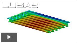
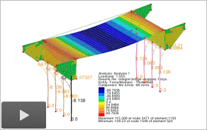
Beam
and shell slicing of results for a composite bridge deck (5:14)
|
|
|
|
LUSAS eigenvalue frequency analysis using the loading to mass facility (2:19)
-
Following an initial linear analysis, eigenvalue controls are specified in separate analyses, firstly without using the loading to
mass option, and then using the loading to mass
option for comparison purposes. (Version 16.0)
|
|
|
|
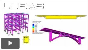
Steel
frame modelling (10:37)
-
Modelling of
a multi-storey steel framed building showing use of
layout grids and generation of columns, bracing and
floor slab geometry. The use of rigid zones to
accurately model steel members is explained together
with the use of floor loading that distributes
floor sub-beam and imposed loads automatically to
supporting perimeter beams. Merging-in of a model of the upper tower is performed to show one of the new
collaboration features. (Version
16.0)
For more
information see Steel
Frame Design.
|
|
|
|
Steel
frame design to EN1993-1-1 Eurocode 3 (6:28)
-
Design code-based combinations
are created followed by
steel frame design attributes that specify member design
values, members lengths and end conditions used in the
determination of buckling capacities. Design checks are
carried out to EN1993-1-1 Eurocode 3 showing utilisation factors and a member
report is created for a selected column to demonstrate the
transparent nature of the LUSAS steel design checking facility
that shows the calculations made, revealing every step,
every clause reference, and every formula. (Version
16.0)
For more
information see Steel
Frame Design.
|
|
|
|
Design of skewed
3-span reinforced concrete bridge deck to Eurocode (13:11)
|
|
LUSAS Version 15
|
|
|
Building a
footbridge model for
linear analysis (9:08)
-
Model
building of a footbridge using point and line features, creation and
assignment of geometric and material properties,
meshing, gravity loading and supports. (Version 15.2)
|
|
|
|
Progressing the
footbridge model
for linear dynamics (6:23)
|
|
|
|
Pedestrian
footbridge
loading assessment to
Eurocode using UK National Annex (13:35)
|
|
 |
Seepage
through an earth dam (14:28)
|
|
 |
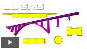
Beam
and shell modelling of a post-tensioned bridge (12:55)
-
Covers the
building of a simple model of a 3-span slab bridge
with twin deep ribs, using shell and beam elements and
constraint equations to tie the surfaces and beams
together to ensure composite action. Tendon profiles
are defined and assigned to the model, requiring
specification of tendon properties, prestress force
and jacking details, and selection of the lines of the
model to which they apply. The deformed shape from
self-weight and prestress loading is viewed for each
in isolation, prior to looking at the effects of both
in a load combination. (Version 15.1)
|
|
 |
Staged
construction modelling of a dam (20:08)
-
Illustrates
the procedures involved in preparing a dam model (that
has been imported from an IGES file) for an initial
linear static structural analysis - as required prior to
developing the model further. The assignment of a
volume mesh to the model, and the applying of
structural material, supports, and gravity loading
only is covered. Activation and deactivation of
elements is used to represent the staged construction
process of pouring individual lifts of concrete. After being solved the stresses in each lift
are investigated. A time-history response graph for a
selected location is produced to show stress changing
with each loadcase. An animation of the construction
stages is produced. A separate model is used to show
heat of hydration modelling involving the use of
thermal material properties with corresponding thermal
temperatures and stresses arising from the analysis
being visualised. (Version 15.1)
|
|
 |
Modelling
and results / reporting overview for a 3-span box
structure (18:15)
-
An initial
import of a DXF and an IGES file showing automatic
meshing and rendering facilities is followed by line
beam modelling of a 3-span box beam structure. The
assignment of user-defined section properties is shown
for standard, linear and tapered box sections, and a
method for finding model geometry without material
assigned is highlighted. Results are viewed for
bending moments and stresses both on the fleshed model
and in a tabular results format. A report is created
showing user-defined outputs and how saved views of
the model and results are automatically updated each
time a report is created. (Version 15.1)
|
|
 |
Interactive
modal dynamics and rail track-structure interaction
analysis (14:04)
-
Overview
of the features and capabilities of the LUSAS
Interactive Modal Dynamics software option (IMDPlus)
with specific reference to rail use, and of the LUSAS
Rail Track Analysis software option, which permits
track/structure interaction analysis to the
International Union of Railways Code UIC 774-3 and to
the relevant sections in Eurocode 1. (Version
15.1)
|
|
 |
Saved
views, results
extraction and report generation (8:50)
-
A simple
integral bridge model is used to show the creation and
use of Saved Views, graphing of results data, the
setting of threshold values for results listings,
one-click member reporting, and auto-updating of the
saved views and one-click member reports for a revised
model. (Version 15.1)
|
|
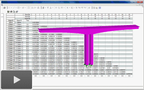 |
Construction
table reporting (5:31)
-
Use of the
LUSAS construction table facility on a box cantilever
model to report tables of displacement data for a
staged construction analysis. Tables shown include a camber table
- as used to set-out a structure towards a target (as-built) profile;
a displacement history table, which reports the absolute displacement of a series of key-points at each stage with reference to an undeformed geometry
'datum'; and an incremental displacement table, which reports the stage-by-stage deformation of a
structure and tabulates the relative displacements between each
stage. (Version
15.1)
|
|
 |
Defining
rigid zones (9:32)
|
|
 |
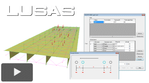
Easy-to-use
lift-off supports and RC slab design to AASHTO (7:36)
|
|
 |
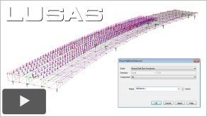
Direct
method influence analysis and Traffic Load Optimisation for
beams to AASHTO (5:51)
|
|
 |
Easy-to-use
lift-off supports and RC slab design to Eurocode (9:32)
-
A simple
bridge model is used to show the use of the multiple
analysis facility, the use of lift-off supports, and
slab design showing bar reinforcement details and
crack checking based on EuroCode 1991-2. (Version
15.0)
|
|
 |
Direct
method influence analysis and Traffic Load Optimisation for
beams to Eurocode (7:37)
|
|
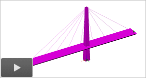 |
Cable
tuning analysis for linear structures (8:15)
-
For many
structures it is vital control the deflected shape
during construction or under imposed loading. Here,
the cable tuning analysis facility is used to
calculate cable forces in a cable stayed footbridge
to meet a user-defined pre-cambered profile, as well
as limiting the main tower displacement and bending
moment to acceptable values. (Version 15.0)
|
|
 |
Modelling
of active/passive soil behaviour with multi-linear joint
material (5:53)
-
Shows a soil-structure
interaction (SSI) problem where structural-element
and ground displacements are dependent upon one
another. An Active / Passive soil joint is set up
for an embedded retaining wall to cater for
lateral pressures increasing with depth, and the
joints are also pre-loaded with an at-rest pressure
at the beginning of the analysis. A parametric
investigation of soil properties and the effects on
bending moments in the wall is also done. (Version
15.0)
|
|
See also:
LUSAS
conference papers and presentations
LUSAS
webinar recordings
|