User Area
> Advice
How do I ensure that my 3D beam elements are oriented correctly?
Unless using completely symmetrical 3D beams in a
LUSAS analysis, geometric properties for 3D thin and thick beams
require the local axes of the beams to be rotated so that the beam
axes lie in a desired orientation.
For example when using 3D thick beams (e.g. element type BMS3)
2nd moment of area properties are required about both the
local beam y and z axes. Therefore the local beam axes must be in the correct
orientation before the analysis is carried out.
If the local beam axes are not explicitly defined by the user
then LUSAS will assign the axes automatically.
However this method is not recommended as the local beam
orientation may not be as required
It is possible to view local element axes from
the “Mesh” layer. Mesh
layer properties can be seen by right-clicking on the Mesh layer in
the Layers tab of the Tree-view and selecting Properties…
The option to “Show element axes” can then be selected and
all local element axes are then displayed if the Apply or OK
button is
pressed. The local x
direction is represented by an arrow with two heads, the local y
direction by an arrow with one head and the local z direction by an
arrow without a head. Local
Cartesian coordinate systems follow the same rules as the global
Cartesian coordinate system and are always in terms of a right-handed
system. The difference
between left and right handed systems is shown in the diagram below.
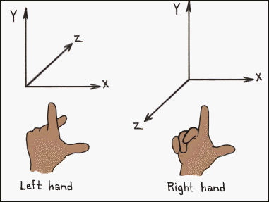
The local element x axis will always be in the
direction of the line representing the beam to which the elements have
been assigned and cannot be changed.
The direction of the axis will point in the direction
determined by the line direction.
The line direction can be visualised by selecting the option
“Line directions” from the Geometry layer Properties window.
Another option is to show the "Line axes".
An example is shown below, note that default the
element axes will follow that of the line (shown by a single pink axes).
In this case the local element axes also correspond with the global
axis as shown.
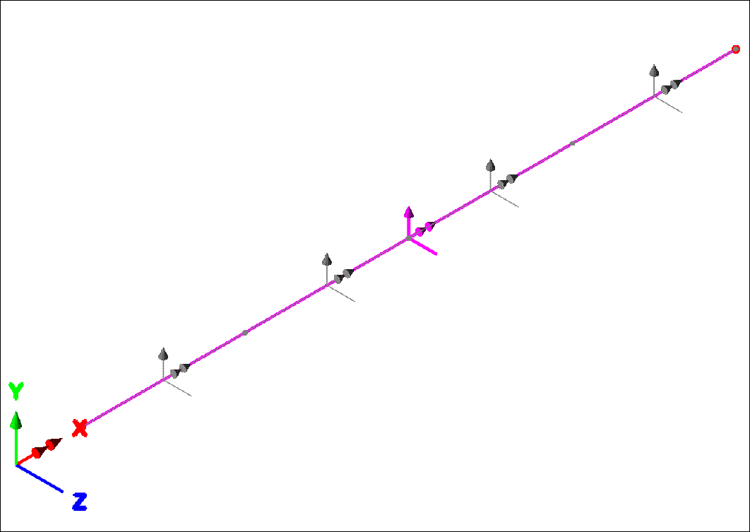
The
local element x direction can be reversed by reversing the line direction,
however the positive direction of the local x axis has no significance
when considering the geometric properties of the beam. The positive z direction of the local z axis is important
when the beam is given an eccentricity value.
Eccentricity is measured from the bending plane to the
nodal line.
In the diagram above, the local coordinate system was determined by
LUSAS when the mesh was assigned to the line, which simply aligned the
local system to be the same as the global system.
This however may not be the correct beam orientation, it may, for
example, be required that the local z direction be pointing vertically
upwards. For this system to
be used the easiest method would be to define a 90 degree angle between
element and line axes, about the x-axis. Such an angle can be
defined on assigning the beam mesh to the line and it is called a Beta
angle.
When the beam element attribute is
assigned to selected lines the following dialog appears:
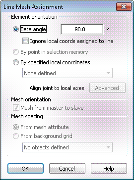
The rotation of the element
axes (grey) 90 degrees about the x axis from the line axes (pink) is shown
below:
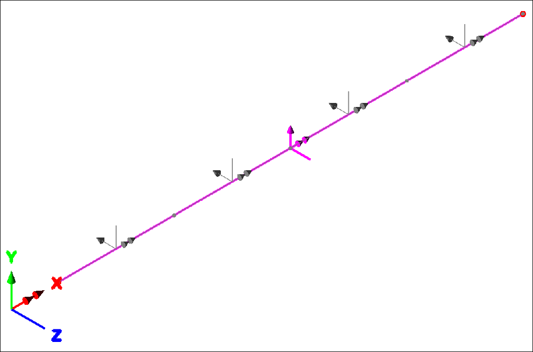
Another method that can be
used requires first define a local coordinate system in
Modeller. A local coordinate
system can be defined using the menu command:
Attributes > Local
Coordinate…
To create the
system as described above a rotation angle of –90 degrees should be
entered which acts about the global X axis (ie in the global YZ plane).
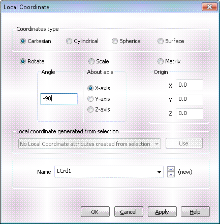
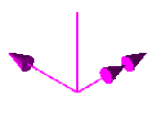 Once defined, the local Cartesian coordinate system will then appear on
the graphics screen at the origin specified in the window.
The coordinate system is coloured magenta to distinguish it from the
global coordinate system. Once defined, the local Cartesian coordinate system will then appear on
the graphics screen at the origin specified in the window.
The coordinate system is coloured magenta to distinguish it from the
global coordinate system.
This local coordinate system can then be used when
assigning beam elements to the lines of the model.
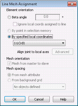
The local coordinate system created earlier can
then be used in the assignment by selecting “By specified local
coordinates”
and selecting the system from the drop-down list.
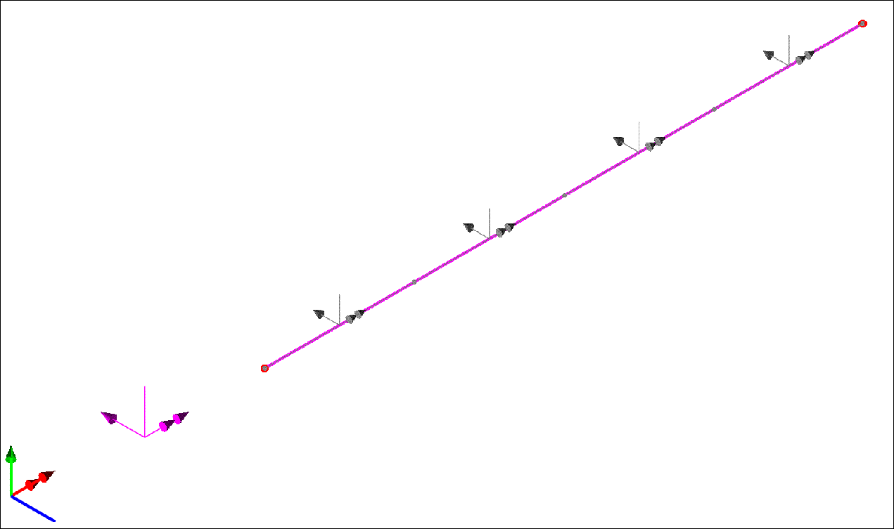
Pressing OK will show that the local coordinate system has been
used in the mesh assignment and that the local element axes are in the
desired orientation.
Joint elements can be oriented
using local coordinate systems in a similar manner.
For more information regarding local
coordinate systems please see following reference:
Modeller Reference Manual >
Chapter 5 : Model Attributes > Other Attributes > Local Coordinates
There is a further
method to orientate the axes. If a point is created and then
selected and put into selection memory (right-click in the graphics
window and choose Selection Memory>Set or Add)
before assigning the Line Mesh, then the option "By
point in selection memory" can be selected.
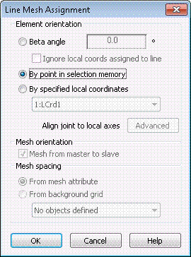
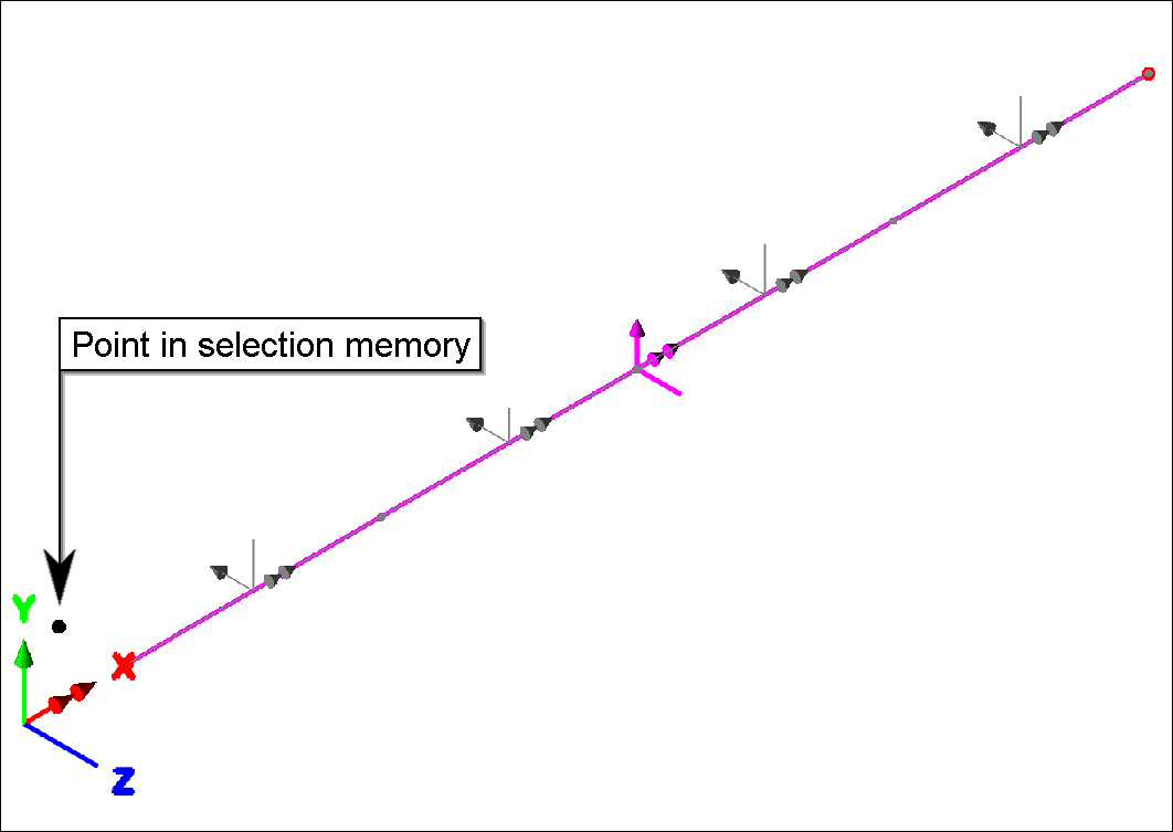
The point is used in
combination with the line assigned to define the XY-Plane. For
the example above where the line runs along the global X axis (Y=0,
Z=0), a point could be created and selected at the coordinate (0, 0,
-1) for example
as shown below.
For more complex
orientation of beam elements there is a script
available to download from the scripts downloads page which may
be helpful.
Notes
-
There are vector rules that are
used to decide the orientation of the line axes, however in general, the
line's z axis will tend to match the global z axis if possible, then the
global y axis, then the global x. Please see the Element Reference Manual
> Appendix C : Local Element Axes > Standard Line Element
-
Local coordinate attributes
should not be assigned directly to a line for the purposes of
orientating beam element axes. This will actually transform nodal
freedoms and will affect the direction of global loads and supports.
|