User Area
> Advice
Using joints at (or between) point features or at line
ends
A point joint mesh can be defined
automatically at the end of a line as an "End condition"
in a Line Mesh attribute, such as a beam mesh.
Attributes > Mesh > Line
> (click button) End conditions...
A joint may be specified at one or
both ends of the line that the line mesh attribute is assigned to
in order that the user can define the connection behaviour using a
joint and a suitable joint material for the behaviour
required. For example, a simple linear joint material such
as "Spring Stiffness" could be used to define a release
for a translational freedom and assigned to the line, and
specified to apply to at the appropriate end of the line. Please
see:
Help > Help Topics >
Contents > Modeller Reference Manual > Chapter 5 - Model
Attributes > Meshing > About Meshing > Beam End
Conditions
Alternatively, an appropriate joint point mesh
can be manually defined and assigned between two selected points in the model.
Attributes > Mesh >
Point > Point Mass or Joint
and select a compatible joint for
the existing mesh. Please
see:
Help > Help Topics >
Contents > Element Reference Manual > Appendix L
for the list of compatible joints
with structural elements, if this approach is to be used.
For
example:
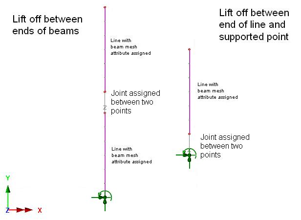
Lift off supports
Whilst lift-off/contact
supports can be easily modelled in either a linear or
nonlinear analysis, simply by choosing the "Lift-off"
option for a particular freedom in a defined support attribute,
there are cases where simple lift-off/contact between mesh
is required or more control over the behaviour is
desired/required. Lift-off (compression only) contact or
supports can also be modelled using joint elements.
Where the point joint mesh is
defined and assigned manually, it can be assigned between the following pair of points:
- A point feature assigned
with a support attribute OR a point feature which is part of any "substructure"
being modelled.
- A point feature at end of line feature modelling column or bridge
beam etc.
Diagram showing joints
between point features
|
|
Tension-only members
Tension
only members such as cables, or compression only
members can be adequately modelled with a single bar
element and using the Tension / Compression Only
piecewise linear bar material.
Attributes >
Material > Tension / Compression Only (Bar)
However, where elements
other than bars are to be used tension or compression only
behaviour can be modelled using joint elements at a
connection.
The point joint mesh is assigned
between the following pair of points:
- A point feature at end of line feature modelling
cable
- A point feature which is part of the rest of the
structure e.g. end of line feature modelling a bridge beam (or a
supported point).
Diagram showing
joint
between point features
|
 |
The point
features which have been generated must be made
"unmergable".
Joints
assigned between sets of selected points
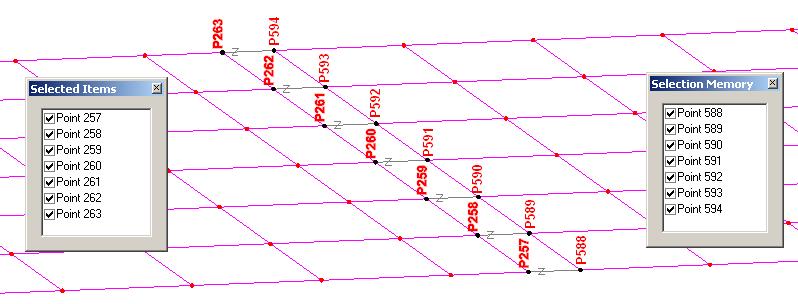
A
joint mesh can also be assigned to two sets of points. One
set is selected and set in selection memory:
(right
click) [Graphics Window] > Selection Memory > Set
or
alternatively: Edit
menu > Selection Memory > Set
The
other set of points is selected in normal selection. The
joint mesh is then assigned. Selecting the option to "Mesh
from master to slave" will make the set of points in
normal selection the 'Master' assignments to which joint geometric
and joint material attributes are assigned. The joint mesh
will be paired between the points in selection and those in
selection memory. The pairing of points is determined either
by the order in which they were selected (if selected by picking),
or in numerical order (if simply box selected).
Diagram
illustrating the assignment
of joints between
set of points selected
Making
points unmergable
The point
features which have been generated must be made
"unmergable", which means that when they share the same
coordinate positions they are not merged automatically by LUSAS
Modeller. You can do this by selecting the features and using the
menu items:
Geometry
> Point > Make unmergable
Joint elements have no length in a stiffness matrix and so any length given in the model will introduce an inaccuracy in the length of any substructure features and will trigger a warning in
the LUSAS Solver text output file (*.OUT). However, moving the point features at each end of joint elements to be coincident can make it difficult to be sure of the orientation of the joints element axes (local x, y, z). Therefore it is prudent always to use a local coordinate dataset to control the
axes, as described in the article on Mesh attributes
How do I model
lift off supports? (main page)
How
do I model tension only members? (main page)
How
do I model a hinged connection between shell meshed surfaces? (main
page)
|
