User Area
> Advice
How do I define a point mass?
In
V14 there are two ways to define a point mass. The easier
option is to use:
Attributes > Mesh > Point > Point
Mass or Joint > Non Structural Mass
This could be
assigned to points that are part of the model.
In LUSAS you can also use line and surface mass only
elements in addition to point mass elements.
These
specific lumped mass elements are for distributed lumped mass.
The
mass element appear as Non-Structural mass in the mesh description
field when defining the mass element dataset. See LUSAS Element
Reference Manual for further details of the mass elements. In
general they are as follows:
Point
(PM2, PM3)
Line
(LM2, LM3, LMS3, LMS4)
Area
(TM3, TM6, QM4, QM8)
After
defining the mesh, you need to assign a material to the Mass elements
too. For this purpose define mass via:
Attributes >
Material > Specialised > Mass
This
material attribute is then assigned to the
relevant features.
The
second option is to use a joint element at the desired location
-
Create a new point near to each point
at which the lumped mass is required. In this instance
a gap between the two joint nodes is not significant in
fact it is actually helpful when assigning the mesh/material
properties.
-
Define an appropriate joint element
point mesh.
1 element division is automatically used
for a joint point mesh.
-
Define a local coordinate attribute
such that (preferably) the local x direction lies along
the length of the joint.
-
Assign the mesh to both
points. On the mesh
assignment form choose the option to select the
local coordinate dataset. Don't assign the local
coordinate dataset directly to the line as this has a different
effect and purpose. The local coordinate system is needed because
the joint elements and their stiffnesses/masses work in
local coordinates, hence, specifying it directly lets
you know which stiffness/mass operates in which direction.
-
Define a joint geometric attribute and enter a value
of zero for eccentricity if none is required.
-
Assign the joint geometric attribute to the
points (only really required on the 'Master' assignment
points).
-
Define a joint material (use "General"
properties). The material properties defined are
in terms of the local coordinate system used in the
joint mesh assignment. Local element axes can be
visualised by selecting the option "Show element
Axes" from the Mesh layer in the Layers tab of the
Treeview. The stiffnesses should be input
as zero and the masses in accordance with those
required.
-
The mass location is dependent on the
order of the points selected. The first node corresponds
to the first point that was selected when defining the
joint. The first point is where the joint
mesh marker is displayed (a Z symbol by default). Make sure that the mass is operating at the correct
location (pay attention to the Mass Position in the input
dialog).
-
Assign the joint material to
the points (only really required on the 'Master'
assignment points).
-
Fully support the new point that you
defined in step 1 above.
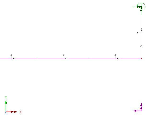
In the image below the horizontal line has been
assigned with 3D thick beam elements. The vertical line
represents the joint to which the lumped mass has been added.
Note the local coordinate system definition and the local element axes
for the beam and the joint element. The mass has been applied at
the first node and therefore at the end of the beam. The point
at the other end of the line has been fully fixed.
|
