User Area > Advice
The Current Stiffness Parameter
The current stiffness parameter (cstif) is
output to the nonlinear log file and is a useful measure of the degree of nonlinearity
being experienced by a structure. In its simplest, unscaled form it effectively measures
the stiffness (k) of the system as related to the initial tangential predictor.
Alternatively stated it is the ratio of the current stiffness of the structure to its
initial stiffness. The unscaled stiffness is evaluated according to
k = Dq/Dp
or scaled (to account for the vectorial nature of the Dq and Dp components) as
k = (DqT Dp)/(DpT Dp)
where Dq is the incremental applied load
vector and Dp, the resulting tangential displacements. LUSAS
then computes the cstif parameter as follows
cstif = k/k0
Where k0 is the initial k value evaluated at the initial
iteration of the first load increment.
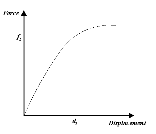
The term tangential refers to the momentary stiffness value of
the overall structure. For instance, consider an overall force-displacement response for a
structure as follows…

The value of stiffness at a force ft
and displacement dt is the tangential stiffness at that point -
the magnitude being evaluated from the gradient which is tangent to the curve at that
point.
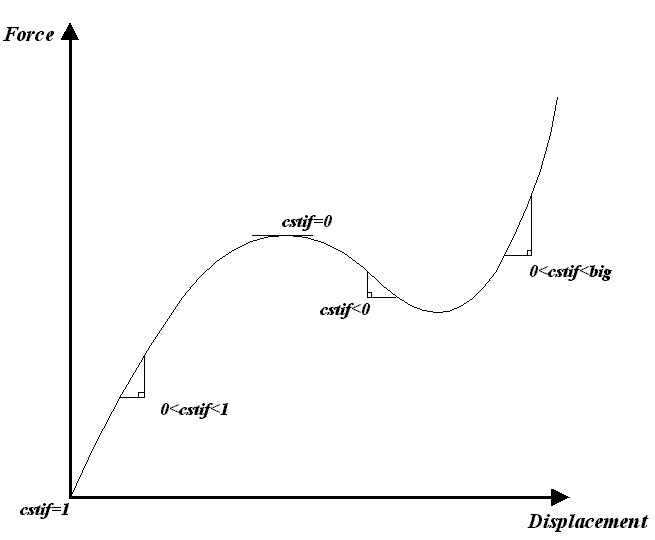
Consider the following force vs displacement response:

From which the following comments made be made…
- cstif may be negative, positive or zero and may vary between the maximum
positive and negative real values for the computer
- A positive value indicates a "hardening" stiffness whilst a negative
value indicates "softening"
- For "force" loading cstif represents the equivalent tangential
stiffness of the overall structure
- For incremental or total prescribed displacement loading, the tangential loading
is zero and, hence, cstif does not give any useful information
- cstif will be unity on the 1st iteration of the 1st
increment of the solution
- Many structures exhibit a response in which the
structure softens as the load is applied. In such situations,
it is very useful to force the solution procedure to automatically
switch from load control to arc-length control as the
limit point is reached. Because cstif is known
to be zero at such a point, the introduction of a suitable
value of cstif below which this switch is automatically
introduced is possible. This is supported in LUSAS and
the parameter can be set by specifying the "stiffness
ratio to switch to arc-length". The default threshold
is taken as 0.4. If the arc-length variable (isurf)
equals unity then the arc-length procedure has been invoked.
- Stress stiffening or second order strain effects associated with geometric
nonlinearity may result in large values of cstif
- The rate of convergence will normally decrease as cstif approaches a zero
magnitude
A number of implications regarding the state of the analysis may be
derived according to the CSTIF value, and are as follows:
CSTIF Magnitude |
Implication |
| Approximately 1 |
- The overall stiffness of the structure has remained unchanged by the
effects of the nonlinearity
|
| 0 < cstif < 1 |
- Typically indicates a softening behaviour, but may also be post yield
and/or pre-buckling behaviour
|
| Zero |
- A "limit" or "saddle" point has been reached
- An element or global mechanism has been excited
- Catastrophic material failure. This may indicate incorrect nonlinear
material parameters
- The buckling load level has been reached
- Contact or other load reaction mechanism has been lost
|
| cstif < 0 |
- Unloading is occurring
- Softening as a result of material nonlinearity. Significant softening may
indicate incorrect nonlinear material parameters
- Post buckling behaviour
- Contact and any other load reaction mechanism has been lost
|
| cstif > 1 |
- Hardening behaviour
- Post buckling behaviour
- Stress stiffening influence becoming significant
- Material locking under large plastic strain
|
| Sudden changes |
- Too large a load increment
- Too slack a convergence tolerance
- Data error
|
|