User Area > Advice
Element quality
It is essential that a
finite element solution should converge to the “exact” solution as the number of
elements is increased (where “exact” is measured according to assumptions made
in the model). Moreover, the convergence should also be monotonic, that is converging from
one direction only - not oscillating in some manner about the exact solution. The
following diagram shows both monotonic and non-monotonic convergence.
The basic requirements
for guaranteed monotonic convergence are
-
The displacement function should
be such that it does not permit straining of an element to occur when the nodal
displacements are caused by rigid body displacement. This is self evident, since an
unsupported structure in space will be subject to no restraining forces
-
The displacement function should
be of such a form that if nodal displacements produce constant strain conditions such
constant strain will be obtained. This is essential since significant mesh refinement will
cause near-constant strain conditions to occur in elements and they must be able to handle
this condition correctly
-
The displacement function should
ensure that the strains at the interface between elements are finite (even though
indeterminate). By this, the element boundaries will have no “gaps” appear
between them and, hence, will show a continuous mesh.
These are satisfied
by all elements in LUSAS when they are of a general (but admissible) geometric shape. The
recommended mesh sensitivity tests to ensure that the analysis results are not affected by
mesh coarseness rely on this being true.
The slope of the convergence curves in the previous diagram measure the
rate at which mesh refinement attains the exact solution. The magnitude of the slope is
determined by the order of the elements used in the mesh – higher order elements
providing faster convergence than low order.
It has been found,
however, that the rate of convergence for a given element (low or high order) and for any
size (large or small) is significantly dependent on the degree of geometric distortion
present in both its undeformed and deformed states. This effect is due to the elements no
longer being able to represent the same order of displacement polynomial after the
geometric distortion as they did without the distortion.
The following table
summarises the effects of various element distortions on the 8-noded plane continuum
element, a similar effect is seen on most other elements.
Undistorted, aspect or parallelogram distortion (if
unrotated) |
Undistorted, aspect or parallelogram distortion (if rotated) |
Angular distortion |
Excessive midside node distortion |
1, x, y, x2,
xy, y2, x2y, y2x |
1, x, y, x2,
xy, y2 |
1, x, y |
1, x, y |
The first column in the table gives the displacement field that
can be exactly modelled by the element when the element is undistorted and unrotated or is
subjected to an aspect ratio or parallelogram distortion only. The second column is
similar but includes the effect of general element rotation.
What is most
noticeable is that an angular or midside node distortion significantly reduces the
predictive capability of these elements. With such distortions the elements can represent
only linear displacement variations in x and y exactly compared to the original quadratic
capability.
The definitions of
these element distortions are presented in the following diagrams:
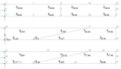
An example of the
effect of angular distortion is seen when considering a simple cantilever beam modelled
with plane elements and loaded with a moment on the free end. The top picture represents
the correct results obtained at Gauss points when using an undistorted mesh of 8-noded
elements and integrated with a 2x2 rule. The middle picture shows the results
obtained with distorted 4-noded elements and the bottom picture, the results from the
distorted 8-noded mesh.
For
this reason LUSAS writes WARNING messages to the output file
when (a) midside nodes are not centred
sufficiently, (b) excessive midside node distortion is present
and (c) element aspect ratios
exceed a default limit.
It
is also essential to view unsmoothed
contours to detect significant discontinuities at element boundaries
(since it is difficult to construct a robust test for angular
distortion and rotated configurations).
Additionally, the
convergence rate of elements is reduced in the presence of localised singularities as a
result of, for example, the presence of single point loads or point reactions. In such
cases, errors in both the displacement and stress will be locally infinite, although the
overall solution may well be acceptable. Similar localised behaviour will exist near
re-entrant corners where stress singularities exist in elastic analysis. Such
localisations are significantly ameliorated by modelling sharp corners with a smooth
radius or by applying loading and supports over an area.
Finite
Element Theory Contents
Aspect
Ratio Warnings
The
Jacobian Matrix
Finite
Element Equilibrium
Numerical
Integration
|