User Area
Software Release History - Version 16
New Facilities and Improvements
in LUSAS Version 16.0
Release history
V16.0-3 made available on 13 January 2020
This is an error
fix release to correct an urgent software issue preventing the loading
of any results file generated since midnight 1st January 2021 into
LUSAS Modeller.
Other error fixes and
change requests are included.
V16.0-2 made available on 9 April 2018
This release is an
error fix release for various change requests
- Read the Release Note for full
details of all changes made.
Go to
Software Download page
V16.0-1 made available on 14 November 2017.
Version
16.0 of LUSAS is a major software release that sees the introduction
of steel frame design checking capabilities into LUSAS Modeller and a
host of other new features and enhancements to improve general
usability and make collaboration
between design teams easier.
In addition to steel frame design.
other design code-related improvements and enhancements include those
for reinforced concrete slab design, traffic load optimisation, design
load combinations, and response spectra for various design codes. New
worked examples are provided to show how the new design checking and
design load combinations facilities are used.
- Analysis-related improvements
include the ability to define a cable tuning loadcase in a
nonlinear analysis, the introduction of p-delta analysis
capabilities, time-dependent prestress, and eigenvalue buckling of
stressed structures. A time management facility allows for easy
adjustment of the duration of pre-defined construction stages in a
staged construction analysis.
- Of many new results processing
features, inspection locations, which obtain results for
user-defined positions of interest anywhere on a model are of
particular note, along with enhanced averaging of results, and
improvements to graphing, section slicing and combinations. For
printed results, the Print Results Wizard dialog is now used to
add chapters of selected loadcase results to a model report.
- For general modelling, model
analysis categories have been introduced. Selection of an analysis
category simplifies the user interface to generally only show
those menu items and options that are appropriate to the type of
model being defined - all helping to enhance the modelling
experience and adjust the user interface based on the analysis
category. Models can now be merged together allowing two or more
people to create separate models of specific parts of a structure
simultaneously. BIM import / export is now provided. Section
property calculation now supports compound sections, infilled and
encased sections, and thin walled arbitrary sections defined
solely by lines. Perspective viewing has been introduced, and
layout grids and new point, line and surface drawing options
speed-up the creation of frame models. Temperature dependent
material properties can be defined in LUSAS Modeller for all
materials.
- A range of new 2D and 3D beam
elements that provide more functionality have been introduced,
with some becoming the default elements of choice for beam and
frame analysis.
- An updated user interface provides a
more modern look and feel, provides tabs for window selection
panels, easier ways to interact with the view windows, and permits
multiple selection of treeview data for assignment or deletion
purposes.
In summary, this release
contains the following
enhancements:
Design-related
Traffic Load
Optimisation
Analysis-related
Results-related
|
Modelling-related
Element-related
General changes
New worked
examples
|
Design-related improvements
| New
Design Menu
 A
new Design menu has been introduced for LUSAS Bridge and LUSAS Civil
& Structural software products. Currently it lists menu
items for RC Slab Design, Steel Frame Design, Export to
Steel/Composite Frame Design, and Design Combinations. A
new Design menu has been introduced for LUSAS Bridge and LUSAS Civil
& Structural software products. Currently it lists menu
items for RC Slab Design, Steel Frame Design, Export to
Steel/Composite Frame Design, and Design Combinations.
Steel Frame Design menu items
will be omitted if a model analysis
category of 3D is not in use, and menu items will be
'greyed-out' if your software licence key does not currently
support them.
Please contact your account
manager if you wish to have access to any licensed options,
and are unable to do so. |
|
Steel
Frame Design
Design
code checking of steel members can now be easily carried out
in LUSAS Modeller. This is performed as a results processing
operation following the solving of a model, and the assignment
of Steel
frame design attributes to lines that represent steel
members, in order to provide design related information for a
specified design code.
The
following design codes are currently supported:
- AASHTO
LRFD 7th Edition (2014) - AASHTO LRFD Bridge Design
Specifications, 7th Edition, American Association of State
Highway and Transportation Officials, 2014.
- CSA
S6-14 Canadian Highway Bridge Design Code - CSA-S6-14,
Canadian Highway Bridge Design Code, Dec 2014, CSA Group.
- EN1993-1-1+A1:2014
- EN 1993-1-1:2005 Eurocode 3: Design of steel structures
� Part 1-1: General rules and rules for buildings.
- AS
4100-1998 Steel Structures (Australia) - Australian
Standard: AS4100-1998, Steel structures, Standards
Australia International Ltd, Sydney.
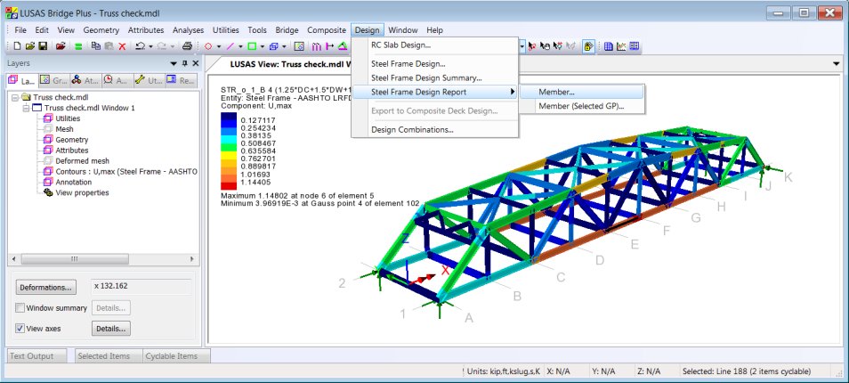
Design
check results are visualised as Utilisation ratios on a
results viewing layer for a selected design code, and active
loadcase, load combination or envelope. Results components for
individual design checks can be chosen for viewing, and
maximum utilisation factors can also be obtained.
Design
summary reports
A
tabular summary of design check results can be produced for
selected members and loadcases. Results may be saved for use
with Microsoft Excel or saved to a text format. Results can
also be added to a model report, and each time the main report
is generated the design summary data will be updated to match
the current state of the model.
Formatted
member reports
To
investigate the design calculations carried out for particular
members,
formatted design reports can be generated, showing the
calculations made and referencing clauses and equations from
the code. A formatted design report for the selected member
can be added to a model report.
New
worked example
|
Design
Code Load Combinations
The new Design Combination wizard is
used to assign a loadtype to a loadcase, envelope or basic combination
for a supported design code. Based on the assignments and settings
made, load combinations for those load types are automatically
generated by LUSAS Modeller, rather than having to be user-defined
one-by-one.
 |
|
 |
| Loadcase
/ loadtype definition |
Combination
options
|
Design
combinations created |
Design
combinations for the following codes of practice are supported.
- AASHTO
7th Edition
- AS/NZS
1170
- BD21/01
- BD37/01
- CSA-S6-14
- EN1990
(Buildings) Recommended Values
- EN1990
(Buildings) to Irish National Annex
- EN1990
(Buildings) to UK National Annex
- EN1990
(Bridges) Recommended Values
- EN1990
(Bridges) to Irish National Annex
- EN1990
(Bridges) to UK National Annex
- GB
50009 - 2012
- JTG
D60-2004
New worked example
| RC
Slab design with bending and in-plane effects
 The
reinforced concrete slab design facility has been improved to
consider in-plane effects for structures modelled using shell
elements. It supports plotting of contours and values that
indicate flexural reinforcement requirements at Ultimate Limit
State (ULS) or design crack width at Serviceability Limit
State (SLS) for design codes that support this. Calculations
now carried out are for reinforced concrete slabs (without
prestressing) that are modelled using plate or shell elements.
For ULS, both bending only (using Wood-Armer), and bending and
in-plane effects (using Clark-Nielsen) can be considered. For
SLS, both bending-only (using principal moments), and bending
and in-plane effects (using principal stresses) can be
considered, if supported by a chosen design code. The
reinforced concrete slab design facility has been improved to
consider in-plane effects for structures modelled using shell
elements. It supports plotting of contours and values that
indicate flexural reinforcement requirements at Ultimate Limit
State (ULS) or design crack width at Serviceability Limit
State (SLS) for design codes that support this. Calculations
now carried out are for reinforced concrete slabs (without
prestressing) that are modelled using plate or shell elements.
For ULS, both bending only (using Wood-Armer), and bending and
in-plane effects (using Clark-Nielsen) can be considered. For
SLS, both bending-only (using principal moments), and bending
and in-plane effects (using principal stresses) can be
considered, if supported by a chosen design code.
Reinforcement arrangements are
now defined using RC
slab design attributes. Multiple slab design attributes
may be defined and assigned to relevant features on a model.
Values and results contours for
a chosen results component can be displayed for a stated slab
face and for a previously chosen Code of Practice using
standard values and contour plotting facilities. |
RC
Slab design to AASHTO LRFD 7th
The RC slab design facility now
supports AASHTO LRFD Bridge Design Specifications, 7th Edition,
American Association of State Highway and Transportation Officials,
2014.
| Wood-Armer
attribute
 The
introduction of Wood-Armer attributes simplifies the
specification of slab reinforcement arrangements. When
assigned to features in a model, they permit calculation of
top and bottom reinforcement moments for shell, plate and
grillage elements, and top and bottom reinforcement forces for
shell elements only according to Wood-Armer / Clark-Nielsen
theory. Multiple Wood-Armer attributes may be defined and
assigned to relevant regions and features on a model. The
introduction of Wood-Armer attributes simplifies the
specification of slab reinforcement arrangements. When
assigned to features in a model, they permit calculation of
top and bottom reinforcement moments for shell, plate and
grillage elements, and top and bottom reinforcement forces for
shell elements only according to Wood-Armer / Clark-Nielsen
theory. Multiple Wood-Armer attributes may be defined and
assigned to relevant regions and features on a model.
|
| Response
spectra provided for numerous design codes
Design code
response spectrum data for use with IMD loadcases can be
defined by selecting the general Utilities > Response
Spectra menu item. The following codes of practice are
currently supported:
- ASCE
7-10 (2010)
- ATC-40
(1996)
- China
GB 50011-2010
- EN1998-1:2004
Design (Horizontal)
- EN1998-1:2004
Elastic (Horizontal)
- FEMA
356 (2000)
|
Material
library enhanced
Supplied library materials are now
accessed by choosing a material type, for a region or country (when
applicable), for design code or standard (when applicable), and for a
grade of material (when applicable). Defined material can now be named
explicitly, rather than have just a system generated name assigned to
it, as in previous versions.
For some materials in some regions a
user-defined grade can also be specified. An example of this would be
for Concrete, USA, AASHTO LRFD 7th, where a compressive strength,
weight, aggregate correction factor, and cement type can be defined.
LUSAS Traffic load optimisation improvements
China
JTG D60-2015
When the country name 'China' and
Design Code 'JTG D60-2015' is selected on the Vehicle Load
Optimisation dialog, traffic loading can now be generated according to
China standards:
- JTG
D60-2015 General Code for Design of Highways Bridges and Culverts,
Chapter 4: Actions.
Denmark -
DS/EN 1991-2 DK NA:2015
When the country name 'Denmark' and
Design Code 'EN1991-2 Denmark 2015' is selected on the Vehicle Load
Optimisation dialog, traffic loading can now be generated according to
Denmark standards:
- EN
1991-2 DK NA:2015 DS/EN 1990/A1 DK NA:2015 National Annex to
Eurocode 0: Basis of structural design, Annex A2 Applications for
Bridges, BaneDanmark/ Vejdirektoratet, 27 Apr 2015.
-
DS/EN 1991-2 DK NA:2015 National
Annex to Eurocode 1: Actions on structures � Part 2: Traffic
load on bridges, BaneDanmark/ Vejdirektoratet, 1 May 2015
-
Annex A (Normative) Load Models for
Classification and Assessment of Load-carrying Capacity,
BaneDanmark/ Vejdirektoratet,
Saudi Arabia -
MOMRA Bridges Design Specifications
When the country name 'Saudi Arabia'
and the Design code 'MOMRA', is selected on the main Vehicle Load
Optimisation dialog, road traffic loading data and parameters can now
be specified with reference to MOMRA Bridges Design Specifications.
Sweden TDOK
2013_0267 (NATO Vehicles)
When the country name 'Sweden' and
Design code 'TDOK 2013:0267 Military Vehicles' is selected on the main
Vehicle Load Optimisation dialog, vehicle loading can now be generated
to aid with military load classification of bridges with reference to
clauses 2.2.1.5 and 1.3 of TDOK 2013:0267 Version 3.0 - B�righetsber�kning
av broar. UHabb January 2016.
United
Kingdom - BS5400-2:1978 loading added
When the country name 'UK' and Design
code �BS5400-2:1978� is selected on the Vehicle Load Optimisation
dialog, main road traffic loading can now be generated to
BS5400-2:1978 Steel, concrete and composite bridges Part 2:
Specification for Loads, incorporating Amendment No 4209. British
Standards Institution, March 1983.
United Kingdom
- BD37/01 loading added
When country �UK� and Design code
'BD37/01' is selected on the main Vehicle Load Optimisation dialog,
road traffic loading can now be generated with reference to BD37/01.
United
States of America - AASHTO LRFD 7th Edition: Additional State
Implementations
When country �USA" and Design
code �AASHTO LRFD 7th Ed. - <State>" is selected on
the main Vehicle Load Optimisation dialog, road traffic loading can
now be generated with reference to the following new implementations:
- Indiana
- Indiana Design Manual (2013), Indiana Department of
Transportation. The ability to choose state-specific
Permit/Owner-specified vehicles is included on the Optional Code
Settings dialog.
- Louisiana
- LRFD Bridge Design Manual No 2 (June 2016), Department of
Transportation and Development, State of Louisiana. The option to
apply or not apply magnification factor (LADV-11 loading) is
allowed for. When applied, an extra column in the influence dialog
is provided to input the magnification factor (MF) for each
influence.
- Maine -
MaineDOT Bridge Design Guide (March 2014). The ability to choose
between �Maine modified live load� or �Normal HL-93 live
load�, for the Strength I design case is allowed for on the
Optional Code Settings dialog.
- Minnesota
- LRFD Bridge Design (May 2016) Minnesota Department of
Transportation. The ability to choose between 125% or 110% of
HL-93 is provided in the Optional Code Settings dialog. Also the
option of 90% of HL-93 (general AASHTO) is given.
- Nevada -
NDOT Structures Manual (May 2014). The ability to choose
state-specific Permit/Owner-specified vehicles is included on the
Optional Code Settings dialog.
- New York
- NYSDOT LRFD Bridge Design Specifications, September 2011.
Analysis-related improvements
Nonlinear
cable tuning loadcase
 The linear cable tuning analysis
facility (which calculates load factors for selected lines in a model
that represent cables in order to achieve defined target values for
various results components) has been supplemented by a nonlinear cable
tuning loadcase option. This can be configured by selecting the Analyses> Nonlinear
Cable Tuning Loadcase menu item. The linear cable tuning analysis
facility (which calculates load factors for selected lines in a model
that represent cables in order to achieve defined target values for
various results components) has been supplemented by a nonlinear cable
tuning loadcase option. This can be configured by selecting the Analyses> Nonlinear
Cable Tuning Loadcase menu item.
Nonlinear cable tuning is for use in
nonlinear analyses where geometric, material or boundary condition
nonlinearity may exist. It is also used for obtaining an equilibrium
state of stressed geometry in existing structures when nonlinear
effects are significant.
Unlike
linear cable tuning, loadcases do not have to be explicitly selected
to be included in a nonlinear cable tuning analysis. Instead, the
position of a nonlinear cable tuning loadcase within the Analyses  Treeview will dictate which preceding loadcase is used to provide
loading data for the cable tuning analysis.
Treeview will dictate which preceding loadcase is used to provide
loading data for the cable tuning analysis.
P-Delta
analysis
P-Delta analysis has now been
implemented for bar, beam, thick and thin shell, and 2D and 3D
continuum elements with GNL capability. P-Delta analysis is an
approximate geometrically nonlinear (GNL) analysis typically used to
take account of the interaction between vertical and horizontal (sway)
loading on tall, slender buildings. Vertical constant loads (usually
dead loads) are used to form the geometric stiffness (stress
stiffened) matrix for the structure; additional live load cases can
then be applied and load combinations used to capture the effects of
the interaction between lateral and vertical loading.
Time
dependent prestress
The multi tendon prestress wizard has
been updated for the AASHTO and Eurocodes to provide an option to
allow for producing details and results of losses at any time, and for
any stage of construction, for supported design codes.
 Selection of the new 'Losses based upon
time inputs and calculated stresses' option simplifies and avoids the
previous need to duplicate particular values for Age, material and
geometric attributes that were assigned to the loaded beam. Codified
equations are now used to compute creep and shrinkage coefficients
that were previously difficult for users to define. Values of
"stress at transfer" and "change in stress after
transfer" are now computed from assigned model data by solving
the model at least twice. In doing this, for an initial solve (the
pre-solution), the stress at transfer is assumed to be zero, all
time-dependent losses are assumed to be zero, and the prestress loads
calculated accordingly. In the second (or subsequent) solve, the
stress at transfer is calculated using the eccentricity of each
sampling point, and stresses in concrete read from the results of the
corresponding loadcase in the first (or previous) solution. Selection of the new 'Losses based upon
time inputs and calculated stresses' option simplifies and avoids the
previous need to duplicate particular values for Age, material and
geometric attributes that were assigned to the loaded beam. Codified
equations are now used to compute creep and shrinkage coefficients
that were previously difficult for users to define. Values of
"stress at transfer" and "change in stress after
transfer" are now computed from assigned model data by solving
the model at least twice. In doing this, for an initial solve (the
pre-solution), the stress at transfer is assumed to be zero, all
time-dependent losses are assumed to be zero, and the prestress loads
calculated accordingly. In the second (or subsequent) solve, the
stress at transfer is calculated using the eccentricity of each
sampling point, and stresses in concrete read from the results of the
corresponding loadcase in the first (or previous) solution.
The method of defining prestress prior
to this release can still be accessed using the 'Approximate losses,
requiring input of estimated stresses' option which allows for
producing details and results of short term and long term losses only.
Time
management facility
 The time management facility provides
the means to manage a simple construction schedule and easily adjust
the duration of pre-defined construction stages in a staged
construction analysis. It can be accessed using the Bridge> Time
Management menu item. It can also be accessed from the Tendon
Loading Assignment page of the MultipleTendon Prestress Wizard. The time management facility provides
the means to manage a simple construction schedule and easily adjust
the duration of pre-defined construction stages in a staged
construction analysis. It can be accessed using the Bridge> Time
Management menu item. It can also be accessed from the Tendon
Loading Assignment page of the MultipleTendon Prestress Wizard.
It can be used to easily and
automatically update the total response time values in nonlinear and
transient controls that have been previously specified for each
loadcase of a staged construction analysis.
Eigenvalue
buckling of stressed structures
The current linear buckling analysis
facility has been extended so that it is now possible to define loads
that remain constant (dead loads) and those that can vary (live loads)
for the computation of a load factor to cause buckling. Linear
buckling analysis can now also be carried out after a static nonlinear
analysis.
Conversion
of loading to mass for eigenvalue analysis
 It is now no longer required to
manually convert loading to mass if any semi-permanent loading is to
be taken into account as part of an eigenvalue analysis. Instead an
option on the eigenvalue control dialog can be selected to
automatically make allowance for this loading. It is now no longer required to
manually convert loading to mass if any semi-permanent loading is to
be taken into account as part of an eigenvalue analysis. Instead an
option on the eigenvalue control dialog can be selected to
automatically make allowance for this loading.
Only loading acting in the direction of
the vertical axis is considered.
Results related improvements
Inspection
Locations
 Inspection locations provide the means
to obtain results for user-defined positions of interest on a model.
Model features can have multiple inspection locations assigned to
them. Inspection locations can report results on elements that belong
to the assigned feature, and also those elements that belong to
topologically connected features. Results can be viewed for all
defined inspection locations by selecting the Inspection Locations
option from a relevant results dialog, or for individual chosen
locations. Inspection locations provide the means
to obtain results for user-defined positions of interest on a model.
Model features can have multiple inspection locations assigned to
them. Inspection locations can report results on elements that belong
to the assigned feature, and also those elements that belong to
topologically connected features. Results can be viewed for all
defined inspection locations by selecting the Inspection Locations
option from a relevant results dialog, or for individual chosen
locations.
Improved
averaging of results
 Results averaging rules can now be
accessed via the Model Properties dialog or the Model Properties
control object Results averaging rules can now be
accessed via the Model Properties dialog or the Model Properties
control object  in the
Analyses Treeview. Averaging rules are common for all analyses. in the
Analyses Treeview. Averaging rules are common for all analyses.
By default in LUSAS Modeller, averaging
of results is done for all situations where it is appropriate. Where
averaging is inappropriate, multiple values instead of an averaged
value are now displayed. The new Averaging Options dialog allows users
to state when averaging rules should and should not take place between
adjacent pairs of elements in line, surface and volume features.
Enhanced
averaging for Direct Method Influence analysis
The former requirement in Version 15 to
specify unaveraged or averaged influence results for each
participating element when defining an Direct Method Influence
attribute has been removed. Instead, for Version 16, this decision
will be made automatically. See Model
Properties - Options (Averaging Options) dialog.
Influence attributes defined in and
assigned to a model in Version 15 are unaffected by this new behaviour
because the type of results averaging method that was specified at
the time the influence attribute was generated is defined within
the attribute.
Selective
Results Output
Following results calculation for the
whole model, the results written to a results file can be stated to
either be for all elements, or now, for a specified subset of elements
(those part of a group) within a model. Choosing the latter produces
smaller results files more quickly than would be created for a whole
model.
Improvement
to Graph through 2D facility
A slice section can now be created with
reference to a selected line, arc or combined line, optionally
specifying that the projected length of the line (in a chosen
direction) be used to define the length of slice section line on the
model. In addition line sections can be created from intersecting
surfaces (advanced use) or at the location of an existing graphed
location. When defining the line section by cursor or for lines
generated by projection, the section line created will, by default, be
drawn in the Utilities layer. This may be used later for repeating the
cut if a graph along the same line is required.
A 'Width for corridor averaging' value
can optionally be specified to increase the number of results used
when creating a graph of slice results in order to avoid localised
results concentrations.
Improvements
to Beam and shell / slicing resultants
It is now no longer necessary to have
to view a model along one of the primary view axes prior to defining a
slice location on a model. The slice plane and the orientation of the
slice local axes no longer follow the view's rotation axes. Instead,
the local yz slice plane of the slice path is used to create the slice
planes and this defines the slice local axis.
Multiple beam/shell slice definitions
can now be defined in a single model and are saved as utilities within
the model. The definitions have been enhanced to provide more spacing
options and control over the extent of the model to be sliced.
Results are no longer only displayed
immediately after visiting the Slice Resultants Beams and Shells
dialog. Now, when slice locations are defined and results are
available, results for the slice locations can now be viewed by
selecting the Beam/Shell Slice Resultants entity from the results
properties dialogs (Contours, Diagrams etc). The time taken to produce
beam shell slice results has been reduced.
The Print
Results Wizard is now used to select Beam/Shell Slice Resultants
of interest for viewing in tabular form or adding to a model report
Combination
and Envelope facilities now support User-Defined Results
Beam stresses and results components
defined by the User Defined Results facility can now be used as
primary components when calculating and viewing results for
combinations and envelopes.
Name
scoping for User Defined Results
Name scoping (an association of a name
to an entity, such as a component or variable) has now been introduced
into the User Defined Results facility to help clarify the actual
meaning of an included component or variable. Name scoping is optional
as long as there is no ambiguity. The range of functions supported by
the User Defined Results facility has also been extended.
Print
Results Wizard updated
The Print Results Wizard has been
updated to consist of a single dialog containing all possible results
selections.
 The use of the Print Results Wizard is now consistent with
the Graphs and Saved Views facilities with regard to the way in which
generated data can be added to reports by either using: The use of the Print Results Wizard is now consistent with
the Graphs and Saved Views facilities with regard to the way in which
generated data can be added to reports by either using:
- An Add
to Report button
 on the printed results window that is displayed.
- An Add to Report
context menu for the Print Results Wizard
 entry in the Utilities
  Treeview
The summary facility now presents its
output in a consistent, copy and paste friendly, format.
Loadcase
results now generated in a model report using the Print Results Wizard
facility
The Print Results Wizard dialog is now
used from within the 'Add or Edit a Results Chapter' dialog of the
Report facility to add chapters of selected loadcase results to a
model report.
Progress
bar introduced for Modeller results calculation
A progress bar is now displayed at the
bottom of the user interface to show the approximate progress being
made by LUSAS Modeller in calculating results for a particular
task, such as creating a design envelope, or combination. Each
progress step represents one results component being calculated for
one constituent loadcase.
Improved
storing of Modeller-calculated results
Results for Modeller-calculated results
components (such as those calculated for combinations and envelopes,
and also for other derived components such as design code-based
utilisations, Wood-Amer, user-defined results etc.) can be stored in
order to speed-up the initial and subsequent display of those results.
This can be done either by setting options to store calculated results
in LUSAS Modeller interactively, or by specifying that all or selected
results components should always be stored each time a model is
solved.
Modelling-related improvements
New
Modeller User Interface
The Modeller User Interface has been
updated to provide a more modern look and feel, easier ways to
interact with the view windows, and now supports multiple selection of
treeview data for assignment or deletion purposes.
- View
windows now appear with individual tabs for easy selection. These
can be dragged and dropped within the interface to create
side-by-side views.
- Selection
Memory, Selected Items, Cyclable Items, and Visible Items
selection panels are also tabbed and can be activated and
deactivated individually by using the View > Selection Panels
menu item. These panels can now be dragged and dropped to any
location on screen, docked with other panels and set to Auto Hide,
becoming visible again when the cursor is positioned over their
tab identifier. Double-clicking a docked window will isolate it
again.
- Context
menus for each selection panels can be accessed by right-clicking
on the tab heading for each panel.
- Pre-version
16 window behaviour can be reinstated by selecting the Window> Layout> Multiple
Documents menu item.
Multiple
selection of treeview data
- All
Treeviews (with the exception of the Layers
 Treeview) now support multiple selection of objects in order
to carry-out an operation on the items, such as to delete a range
of loadcases, or to copy attribute data within the treeview.
Treeview) now support multiple selection of objects in order
to carry-out an operation on the items, such as to delete a range
of loadcases, or to copy attribute data within the treeview.
- In the
Analyses
Treeview multiple loading assignments can now be selected to have
their load factors changed to one common value at the same time by
using the 'Change Load Factor' context menu item.
- Other
selection-specific context menus provide options for each treeview
entry. Only appropriate context menu options are provided for
multiple selected items. For instance a 'Deassign' option may be
provided for a particular entry because it would be valid for all
selected objects, but an 'Assign' option would be disabled because
confusion could occur as the additional assignment data (such as
loadcase or analysis) is often required and may conflict.
- Dialogs
that show treeview-style check boxes (such as used in the Print
Results Wizard dialog) now also support multiple selection.
Model
analysis categories introduced
 To prevent potential issues such as
those arising from mixing incompatible elements, and/or mixing
elements with incompatible attributes and options, an analysis
category has been introduced, which must be stated for each model.
Choosing an analysis category of either 2D Grillage/Plate, 2D
Inplane, 2D Axisymmetric, or 3D simplifies the user interface where to
generally show only those menu items, dialog settings and selections
that are appropriate to the type of model being defined. Selecting an
analysis category also defines which startup templates are available
for selection. To prevent potential issues such as
those arising from mixing incompatible elements, and/or mixing
elements with incompatible attributes and options, an analysis
category has been introduced, which must be stated for each model.
Choosing an analysis category of either 2D Grillage/Plate, 2D
Inplane, 2D Axisymmetric, or 3D simplifies the user interface where to
generally show only those menu items, dialog settings and selections
that are appropriate to the type of model being defined. Selecting an
analysis category also defines which startup templates are available
for selection.
Models created prior to Version 16 will
have an analysis category assigned to them automatically by LUSAS when
they are opened (but only where a suitable analysis category can be
established based upon the elements present within the model). If an
analysis category cannot be assigned by LUSAS automatically (perhaps
because a range of now conflicting elements is defined within the
model) a dialog will appear asking for an analysis category to be
chosen.
 Model merge
facility Model merge
facility
Model merge allows two or more people
to create separate models of specific parts of a structure (as for
example for different storeys of a building, or different elements of
a stadium) and then combine them at a later date into one master
model. To do this, a previously saved model can be merged with a
currently-loaded model using the File>
Model merge... menu item. The resulting dialog provides options
to specify how the geometry, attributes, loadcases and groups from the
imported model are to be merged with equivalent objects in the
currently open model.
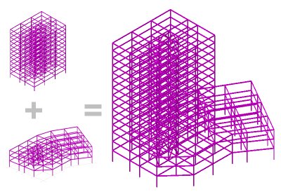
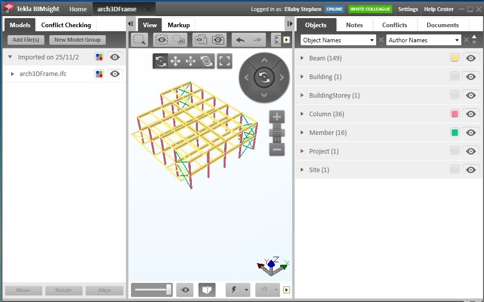 BIM / BrIM File
import / export BIM / BrIM File
import / export
Basic geometry data from third-party
BIM/BrIM files (*.ifc) can be imported to create a feature-based
geometry model in LUSAS. Both BIM/BrIM Structural domain files (*.ifc)
and BIM/BrIM Architectural domain files (*.ifc) are supported for
export.
Compound
section property calculator
 Compound sections can be defined from
existing library sections. These can be positioned relative to each
other and can have differing material properties assigned. The
compound section generated can then be assigned to lines in the model
and fleshed in the same way as any other geometric attributes. Compound sections can be defined from
existing library sections. These can be positioned relative to each
other and can have differing material properties assigned. The
compound section generated can then be assigned to lines in the model
and fleshed in the same way as any other geometric attributes.
Concrete
infilled and encased steel sections
The Infill/Encased Section Property
Calculator is provided in Bridge and Civil & Structural software
products only. The following sections are supported:
 Filled
box Filled
box
- Filled
stiffened box
- Filled
pipe
- Filled
stiffened pipe
- Encased
hollow box - with rectangular or circular encasement
- Encased
filled box - with rectangular or circular encasement
- Encased
hollow pipe - with rectangular or circular encasement
- Encased
filled pipe - with rectangular or circular encasement
- Encased
I-beam - with rectangular or circular encasement
- Encased
Cross I-beam - with rectangular or circular encasement
- Encased
Combined-T-beam - with rectangular or circular encasement
Chinese
steel section library enhanced
Additional cold-drawn, cold-formed,
hot-rolled and welded sections are now available for selection from
the China section library.
| Improved
arbitrary section property calculation
 For thin box sections, only the
points and lines that define the centrelines of the plated
members, and the geometric thickness of each line need to be
initially defined for section property calculation to take
place. Surfaces of a width equal to half of the assigned
thickness are automatically extruded either side of each
line's centreline during the section property calculation
process to determine the correct section properties. These
surfaces can be optionally retained after values are
calculated. For thin box sections, only the
points and lines that define the centrelines of the plated
members, and the geometric thickness of each line need to be
initially defined for section property calculation to take
place. Surfaces of a width equal to half of the assigned
thickness are automatically extruded either side of each
line's centreline during the section property calculation
process to determine the correct section properties. These
surfaces can be optionally retained after values are
calculated.
|
Section
property modification / stiffness reduction factors
Properties affecting the analysis
stiffness of geometric line section properties can now be reduced or
be otherwise modified, whilst leaving their defined dimensions and
section properties intact for design calculations. This is done by
creating section property modifier attributes for each feature type
using the Attributes> Geometric> Section
Property Modifier menu item and then assigning a section
property modifier to selected features for a particular analysis.
Stiffness
reduction factor
A stiffness reduction factor control
option has been provided on the deactivation dialog of the birth and
death facility. This provides control over the amount that the
stiffness matrix is reduced in magnitude when elements are
deactivated. It enables different reductions in stiffness to be
applied to different deactivated elements such that their relative
stiffness is changed, which is useful as a means of controlling the
deactivated elements. For example, it may be desirable for the final
connecting mesh between two cantilevered-out deck ends to have a lower
stiffness reduction factor than the cantilevers whilst deactivated.
Loadcase
dependent constraints
Constraints can now be assigned (and be
turned 'on' and 'off') on a per-loadcase basis. Previously, they could
only be assigned and applied on a per-analysis basis. Amongst many
uses, this will enable the control of the positions of inactive nodes
in a birth and death analysis.
| Perspective
viewing
 A
perspective viewing facility has been implemented in Modeller,
and can be obtained by pressing the Perspective button A
perspective viewing facility has been implemented in Modeller,
and can be obtained by pressing the Perspective button  on the main toolbar. It supports feature selection, resizing,
construction grid and page layout facilities. Using a
perspective view allows for more realistic viewing and
'fly-throughs' of a model.
on the main toolbar. It supports feature selection, resizing,
construction grid and page layout facilities. Using a
perspective view allows for more realistic viewing and
'fly-throughs' of a model.
Parameters to control the view
obtained are set on the View Properties dialog. A viewing
angle, which determines the rate at which the perspective
distortion occurs, and a close depth parameter, which
determines how far in front of the view position objects are
removed from the visualisation, can be set. |
| Layout
grids
 The infinite regular layout
grid of points as provided in previous versions of LUSAS has
been supplemented with a user-definable layout grid. The infinite regular layout
grid of points as provided in previous versions of LUSAS has
been supplemented with a user-definable layout grid.
Layout grids are typically used
to aid with modelling a 2D layout of a structure, but they can
be duplicated to create multiple grid levels for a 3D model as
for example to provide a setting-out grid for each storey of a
building frame. When layout grids are used, points, lines and
surfaces can be defined by cursor with reference to grid
intersections by a variety of methods, doing away with the
need to otherwise enter coordinates for these features. |
| New
point, line and surface drawing options
 A new Geometry > Line> By
Grid menu item allows lines to be defined with respect to
a layout grid. On each
cursor click, a point is created at the nearest grid
intersection. A new Geometry > Line> By
Grid menu item allows lines to be defined with respect to
a layout grid. On each
cursor click, a point is created at the nearest grid
intersection.
New Geometry> Line> By
Grid> Settings and Geometry> Surface> By
Grid> Settings menu items provide access to options to
control how lines or surfaces are created when defining line
or surfaces features with respect to a layout
grid using the new Geometry > Line> By Grid
or the Geometry > Surface > By Grid menu
items.
By clicking and dragging the
cursor to box-select a set of layout grid intersections, lines
or surfaces can be drawn either horizontally in the plane of
the grid, or vertically between grid layouts at selected grid
intersections. |
Section
property modification / stiffness reduction factors
Properties affecting the analysis
stiffness of geometric line section properties can now be reduced or
be otherwise modified, whilst leaving their defined dimensions and
section properties intact for design calculations. This is done by
creating section property modifier attributes for each feature type
using the Attributes> Geometric> Section
Property Modifier menu item and then assigning a section
property modifier to selected features for a particular analysis.
A stiffness reduction factor control
option has been provided on the deactivation dialog of the birth and
death facility. This provides control over the amount that the
stiffness matrix is reduced in magnitude when elements are
deactivated.
Utilities
menu simplified / Tools menu added.
The Utilities menu has been reduced to
now only generally contain those menu items that create a Utility
dataset in the Utilities Treeview. Other items formerly on the Utilities menu now appear on a
new Tools menu, alongside any newly introduced menu items.
Temperature
dependent material properties
Temperature dependent properties of
materials of previously defined, or of new materials can be edited
using the context menu item Edit temperature dependence � for
a material in the Attributes Treeview.
Thermal
loading types rationalised
Thermal loading types have been
reviewed and updated.
Internal
position of shear springs for joint elements with non-coincident nodes
The internal position(s) of the
transverse shear spring(s) for joint elements with non-coincident
nodes can now be defined. Parametric distance factors (between 0.0 and
1.0) can be specified to define the position of the shear spring for
the local y and z directions. This enhancement allows for import of
similar elements from other finite element software.
3D
rotated label and diagram text
Label text for lines and surfaces can
now be optionally drawn to lie along local line axes, or in the local
xy or xz planes.
Similarly, for diagrams, labelled
values can now be drawn in the plane of the diagram, as opposed to
drawing the values flat to the plane of the screen.
Internal
deformed shape of element
LUSAS Solver now computes deformations
at each internal calculation point in each beam element, and these may
be viewed in LUSAS Modeller as contours or a deformed mesh. This means
that the true deformed shape of a line beam can be plotted even if one
line mesh division is used to model the beam. For legacy reasons this
new option is set 'off' by default.
Changes to the Element Library
New 2D
Thick Beam Elements: BMI2 and BMI3
BMI2 and BMI3 are straight and curved
thick beam elements in 2D for which shearing deformations are
included. The elements can accommodate varying geometric properties
along their length. The elements may be used for linear and nonlinear
analysis of two dimensional beam, frame and arch structures.
- BMI2 is
the element selected by default when a 2D Thick Beam linear
element is chosen on the line mesh dialog.
- BMI3 is
the element selected by default when a 2D Thick Beam quadratic
element is chosen on the line mesh dialog.
New
2D Thick Beam Element with Quadratic Cross-section: BMI2X and BMI3X
BMI2X and BMI3X are straight and curved
thick beam elements in 2D for which shearing deformations are
included. The elements have a quadrilateral cross section which may
vary along the element length. The elements may be used for linear and
nonlinear analysis of two dimensional beam, frame and arch structures.
- BMI2X is
the element selected by default when a 2D Thick Cross Section Beam
linear element is chosen on the line mesh dialog.
- BMI3X is
the element selected by default when a 2D Thick Cross Section Beam
quadratic element is chosen on the line mesh dialog.
New
2D Plane Strain Beam Elements: BMI2N and BMI3N
BMI2N and BMI3N are straight and curved
thick beam elements in 2D for which shearing deformations are
included. The element thickness may vary along the length. The element
may be used for linear and nonlinear analysis of two dimensional long
structures of box girder cross-sections such as tunnel linings and
retaining walls for which the plane strain assumption is appropriate.
These elements are compatible with 2D plane strain elements.
- BMI2N is
the element selected when a 2D Plane Strain Beam linear element is
chosen on the line mesh dialog.
- BMI3N is
the element selected when a 2D Plane Strain Beam quadratic element
is chosen on the line mesh dialog.
New
2D Thick Axisymmetric Shell Elements: BXSI2 and BXSI3
BXSI2 and BXSI3 are straight and curved
thick axisymmetric shell elements in 2D for which shearing
deformations are included. The element thickness may vary along the
length. The elements can be used for analysing linear and nonlinear
shell structures which are axisymmetric, e.g. pressure vessels or
pipes.
- BXSI2 is
now the element selected when a 2D Axisymmetric Thick Shell linear
element is chosen on the line mesh dialog.
- BXSI3 is
now the element selected when a 2D Axisymmetric Thick Shell
quadratic element is chosen on the line mesh dialog.
New 3D
Thick Isoparametric Beam Elements with Torsional Warping: BM21W,
BMI31W
Straight and curved beam elements in 3D
for which shearing deformations and torsional warping are included.
The elements can accommodate varying geometric properties along the
length. The elements may be used for linear and nonlinear analysis of
three dimensional beam, frame and arch structures. BMI21W may also be
used as a stiffener for the QTS4 shell element; while BMI31W may be
used as a stiffener for the QTS8 shell element.
New
3D Isoparametic Thick Beam Elements with Quadrilateral Cross-Section
and Torsional Warping: BMX21W, BMX31W
Straight and curved beam elements in 3D
for which shearing deformations and torsional warping are included.
The element has a quadrilateral cross section which may vary along the
element length. The elements may be used for linear and nonlinear
analysis of three dimensional beam, frame and arch structures. BMX21W
may also be used as a stiffener for the QTS4 shell element; while
BMX31W may be used as a stiffener for the QTS8 shell element.
For more information on all these
element types see Element Reference Manual.
Retired
Elements
These elements have been retired
because their use has been superseded by elements with improved
capabilities. Historical models that make use of these elements are
not affected and will still solve. Note that all retired elements do
not appear for selection on drop lists but can still be accessed by
typing the element name into the Line Mesh Attribute dialog.
- BEAM has
been retired and replaced by BMI2, which additionally accommodates
varying thickness, and geometric or material nonlinearity. BMI3 is
also available as a higher order alternative.
- BMS3 has
been retired and replaced by BMI21, which additionally
accommodates varying thickness, product moment of area input (for
non-symmetric sections, strain output, and geometric and material
nonlinearity. BMI31 is also available as a higher order
alternative.
- BTS3 has
been retired and replaced by BMI21, which additionally
accommodates varying thickness,and a higher order variation of
forces and moments along its length. BMI31 is also available as a
higher order alternative.
General changes
LUSAS
installation
The LUSAS installation now follows the
Windows convention.
Changes
affecting LUSAS Programmable Interface (LPI)
All new facilities in Version 16 come
with corresponding extensions to the LUSAS Programmable Interface. See
LPI documentation for more information.
Modeller
Results File caching retired
Modeller Results Files (.mrs) that were
created by LUSAS Modeller to save assembled results and speed up the
results processing of combinations have been retired and have been
replaced in Version 16 with an improved results caching capability.
See Combination
and Envelope Options for more information.
Bridge
load combination wizards for selected design codes retired
The bridge load combination wizards for
the BD37/88, BRO and the Korean Highway codes have been retired. A new
Design Combination wizard facility
has been implemented in their place.
Other
user change requests
In addition to the range of new
facilities and improvements listed, many user change requests have
also been implemented. The originators of all requested changes to the
software (some of which are included in the above list of
enhancements) that have been incorporated in this release will be
notified individually.
Documentation
User manuals
All online and printed documentation
has been updated for this new release. Manuals are provided in PDF
format as part of any Version 16 software download file, and are also
included on the Version 16 software DVD.
New
Worked Examples
The following examples have been
created to illustrate new facilities added in this release.
- Steel
Frame Design to EN 1993-1-1 shows the steps required to
prepare a model for a steel frame design check in accordance with
EN 1993-1-1, and viewing results of member utilisation both as
contour plots and as fully annotated design reports.
- Bridge
Design Load Combinations to EN1990 shows the use of the new
design load combinations wizard to generate factored design
combinations from codes of practice.
Existing worked examples
All examples have been updated to
ensure that the examples match changes made to the software and
incorporate (where possible) new facilities.
Individual worked examples in PDF
format are provided as part of the LUSAS software download file or
release CD, as well as being available from the LUSAS User Area.
Other
Potential
issues opening PDF files referenced in CHM files
On some PCs, and for certain operating
systems, the installation of security updates as released by Microsoft
can affect the opening of PDF files from the table of contents panel
within the CHM file-based help. Any links to PDF files from within
help topic pages may similarly be affected.
If problems are found when attempting
to open these files from within the online CHM file supplied please
note the following:
- Selected
manuals are supplied in PDF format on the installation kit and
these are normally installed into the <LUSAS Installation
Folder>/Programs/PDF_Manuals folder.
- Workarounds/solutions
may be provided by Microsoft during the availability and support
of this particular LUSAS software release.
Previous new facilities and improvements in
this release
None, this is the first release of
Version 16.
|