User Area > Advice
How LUSAS uses PC resources
Memory management | System
Parameters | Output File Statistics | Scratch
files | Dynamic memory allocation | Hardware
| Terms
Physical Memory
This refers to memory that is internal to the computer. It is to be distinguished from
external mass storage devices such as disk drives. Another term for physical memory is
random access memory (RAM) or main memory.
Physical memory currently provides the fastest access rates for transferring and
manipulating data. All software applications are affected by the amount of physical memory
available, and LUSAS is no different. The amount required to give a "workable"
performance depends on the analysis types and model sizes that are to be analysed and
should be considered carefully. At the more computationally demanding end of the spectrum,
a nonlinear analysis involving upwards of 200,000 degrees of freedom may require around
2Gb of physical memory to ensure that the solution remains in physical memory.
Because the computer can only manipulate data that is in physical memory, every program
executed and every file accessed must be copied from a storage device into physical
memory. The amount of physical memory on a computer is crucial because it determines how
many programs can be executed at one time and how much data can be readily available to a
program.
Because computers often have too little main memory to hold all the data they need, a
technique called swapping is used in which portions of data are copied into physical
memory as they are needed. Swapping occurs when there is no room in physical for needed
data. When one portion of data is copied into memory, an equal-sized portion is copied
(swapped) out to make room.
Virtual memory
Virtual memory is an imaginary memory area supported by some operating systems
such as Windows in conjunction with the hardware. Virtual memory
may be thought of as an alternate set of memory addresses that spans both the physical
memory and the available page file (on a local hard drive). Applications use these virtual addresses rather
than real addresses to store instructions and data. When an
application is executed, the
virtual addresses are converted into real memory addresses as required using the memory management unit
(MMU).
The purpose of virtual memory is to enlarge the address space (the set of addresses) that a program can
utilise. For example, virtual memory might contain twice as many addresses as physical
memory, and a program using all of virtual memory, therefore, would not be able to fit in
physical memory all at once. Nevertheless, the computer could execute such a program by moving into
physical memory those portions of the program needed at any given point during execution.
The operating system divides virtual memory into pages, each of which contains a fixed
number of addresses. A page may be stored in physical memory or in the page file. When the
page is needed, the operating system ensures, where necessary, that it is moved into
physical memory, translating the virtual addresses into real addresses.
The process of translating virtual addresses into real addresses is called mapping.
The moving of virtual pages from disk to physical memory is one half of the process known
as paging or swapping. Paging
is required because, for current Windows operating systems, all data processing must occur
within physical memory and to enable applications to run on computers that have less
physical memory than is required by the application.
The following diagram shows an application accessing pages in virtual memory, which is
then mapped by the memory management unit into real addresses. If the real address does
not exist in physical memory a page fault is generated and a paging operation instigated
to move the required data from the page file into physical memory.
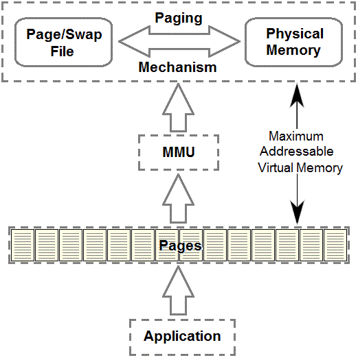
The addressable virtual memory is the maximum amount of memory that can be accessed (or
addressed) by a single application. The amount of addressable memory available to a
program is not necessarily the total amount for the machine. For
32 bit architecture, the limit is 2Gb by default though this can be
increased to 3Gb by editing the operating system's boot
configuration. For 64bit operating systems, a 32bit application
can be run in 32bit emulation mode and can address up to 4Gb (2^32
Bytes).
Data management for a comprehensive software system such as LUSAS is a complex issue.
Reduced to its simplest form, however, it is a question of ensuring that physical memory
is used as much as possible for data manipulation and storage. Although additional
temporary storage is available from the page file, data transfer to and from the hard disk
on which it resides is comparatively extremely slow and to be reduced to a minimum
wherever possible.
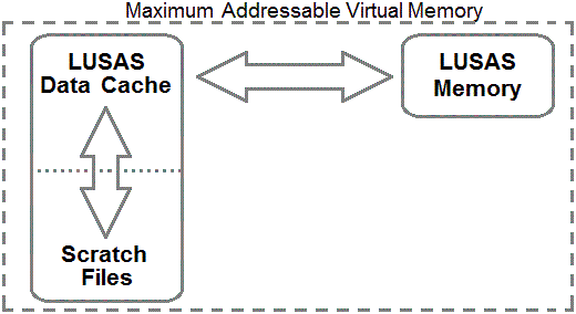
The LUSAS Data Manager
The LUSAS data manager works within the dynamic memory handling mechanisms of the
operating system mentioned above and uses both the physical and page file. It consists of
three main areas, the LUSAS memory, the data cache and the scratch files.
In the same way that data processing must occur within the physical memory, so the
LUSAS data manager is the area of memory in which all LUSAS calculations are performed.
When data is not currently required for processing, it is written to the LUSAS data cache.
This cache stores the most recently accessed data records. As newer data is read into the
cache, so older data is written from the cache to the temporary direct access storage on
disk called scratch files.
The LUSAS data cache is an additional memory area to the LUSAS memory area that should
preferably reside in physical memory (to eliminate thrashing) and acts as a
"buffer" between the LUSAS memory and the scratch files. It attempts to retain
the most frequently used data in the cache to reduce the amount of reading and writing to
the slow access scratch files (disk i/o).
The following inequality must always apply when considering physical memory
requirements
RAM + PAGE FILE > LUSAS MEMORY + DATA CACHE + CONSTANT
Where the CONSTANT value is included to allow for other memory resident programs that
will also be running, the most dominant being the operating system of the computer.
The following diagram shows the data transfer between the three main LUSAS data manager
components:
For optimum solution speed, the memory required by the analysis would be about half the
amount of physical memory available. This will enable the data cache size to be set to
fill up the remaining physical memory. In this way, all the data transfers will take place
within the physical memory and the solution will only be limited by the processor speed.
If an analysis requires all the available physical memory, then the data cache will then
reside on disk in the page file and data transfers between the LUSAS memory and the cache
will require significant disk access.
A number of system parameters are used to control the various components of the data
manager. A list of the most frequently used is given in the table below, together with a
brief description of their effect.
Note that since the release of V15, LUSAS Solver
now makes adjustments automatically and so it should not be necessary to
manually change these System Parameters, unless advised to do so by
LUSAS Technical Support.
| MXELGP |
Maximum number of elements in a group |
| |
During the "assembling elements" and
"recovering stresses" stages of an analysis, LUSAS processes each element in
turn. Rather than request the data for these calculations one element at a time, LUSAS is
able to group element data and process a number of elements at a time. The number of
elements in an element group is determined by the system parameter
MXELGP. Increasing
MXELGP has the effect of reducing the number of times LUSAS needs to access data via the
data manager (typically requiring disk i/o). By default, each group contains 32 elements.
The
theoretically ideal size for this parameter would be the total number of elements in an
analysis. This, however, is usually prohibited by the amount of memory available and a
smaller value should be used.
MXELGP is only applicable for use with LUSAS SOLVER and will be ignored by
MODELLER. |
| NLPZ |
This parameter determines the size of the LUSAS memory in
which all the LUSAS calculations are performed |
| |
NLPZ is specified in terms of real words (locations), where
1 location = 8 Bytes. For example, an NLPZ value of 150E6 locations would allocate
1200 Mb of
physical memory for the LUSAS memory. The number of locations required for each stage of
a LUSAS analysis is output to the output file. Any stage requiring a greater allocation
than specified by the current NLPZ value will automatically invoke a dynamic memory
allocation request to the operating system to expand the total available memory space and
enable the analysis to progress.
The number of locations required for an analysis is entirely problem dependent and
cannot be known accurately prior to the analysis. |
| NPGS |
This parameter determines the maximum number of data
records allowed in the LUSAS data cache |
| |
The data cache size may be calculated from NPGS * 16384
bytes. An NPGS value of 960 would, therefore, correspond to a cache size of
15.7 Mb of
memory. Note that if the data manager cache is increased to such a size that all
information may be retained in the cache without recourse to storing it in a scratch file
(assuming sufficient physical memory), the scratch file sizes will be zero or, in actual
fact, the default record length - usually 16384 Bytes.
|
These system parameters
for Solver are available for modification via the following menu itemin
Modeller:
File> Model Properties...
and then go to the Solver System Variables… tab
However, for users of V15 onwards, it
should not be necessary to edit these settings and it is not generally
recommended.
A summary of the data manager performance for an analysis is given in the statistics at
the end of every Sovler output file. A description of each of the output variables are
given in the following table:
| Disk Unit Name |
The SCRATCH file name |
| Disk Page Size (Bytes) |
The record length of each SCRATCH file |
| Calls to I/O Routines |
The number of calls to the subroutines that interface
between the Solver memory and cache. Each call represents the initiation of one or more
read or write accesses to the data cache from the Solver memory |
| Buffered Transfers |
Each call to the i/o routines may result in one or more
transfers of data depending on the amount of data to be transferred to the cache. The
number of buffered transfers measures the number of copy operations between the cache and
Solver memory. Direct transfers, however, are the number of transfers from the
Solver memory
directly to disk (infrequent) |
| Disk Accesses |
Number of physical disk read or write accesses from the
data manager. Note that, for large NPGS values, the cache may be residing on the disk (in
the page file) anyway. Hence a larger amount of disk i/o will be performed that is not
picked up by this particular parameter |
| Page Table Swaps |
The number of swaps of the page table which have occurred
during an analysis |
| Peak File Size (Mbytes) |
The maximum size of each of the scratch files that occurred
at any time during the analysis. This does not include the scratch files associated with
the multi-frontal solver |
Note: The number of page file
i/o accesses is not available.
Where necessary, the LUSAS data manager stores information in direct access (scratch)
files that also reside on the hard disk. There are a number of such files whose creation
is partly dependent on the type of analysis that is invoked and that will be automatically
created whilst LUSAS is running. The files will be retained on disk if LUSAS is aborted
for any reason. They should be deleted to ensure that available disk space is
maximised.
Their presence, however, will not affect LUSAS performance. The following table describes
the more frequently occurring LUSAS scratch files (typical file extensions are given in
brackets):
| Frontal (.frn) |
Stores element solution records and reduced equations
during the analysis (unformatted, direct access, fixed length records) |
| Shapes (.shp) |
Stores element shape functions during the analysis
(unformatted, direct access, fixed length records) |
| Problem (.prb) |
Stores problem related data, element data and results
records during the analysis (unformatted, direct access, fixed length records) |
| Restart (.rst) |
Stores data at a structure and element level (unformatted,
direct access, fixed length records) |
| Modeller (.mys) |
Contains MODELLER data used for post-processing
(unformatted, direct access, fixed length records) |
| Page table (.pge) |
Used by the database manager to store page table
information when necessary (unformatted, direct access, fixed length records) |
| Multi-frontal (.tmp) |
Stores the global records required for the multi-frontal
solution procedure (unformatted, direct access, fixed length records) |
| Global stiffness assembly
(.gsm) |
Only used for the multi-frontal solver and is used during
the assembly of the global stiffness matrix (unformatted, direct access, fixed length
records) |
| Global mass assembly (.gmm) |
Only used for the multi-frontal solver and is used during
the assembly of the global mass matrix (unformatted, direct access, fixed length records) |
LUSAS Solver will automatically increase the memory allocation during the analysis up to the
maximum amount of memory available.
The choice for hardware upgrades depends on the dominant system bottleneck, which in
turn depends on the type of usage that the system is put to. In the general case, however,
major improvements can be achieved by adding more physical memory and a faster disk
subsystem. When the memory and
disk speed issues are circumvented, the processor speed would then become a significant
factor.
Finally, ensure that LUSAS runs on a local
disk, since network disk access is never as
fast.
-
1 Byte = 8 Bits
-
16 Bits = 1 Word
-
1 Word = 2 Bytes
-
1 Word = 16 bits
-
2 Word = 1 double Word
-
1 Nibble = � Byte = 4 Bits
-
1 Mbytes = 10242 Bytes = 1048576 Bytes
-
1 Gbytes = 10243 Bytes = 1073741824 Bytes
-
16k = 16384 Bytes
-
For LUSAS software:
-
1 Integer Word = 4 Bytes
-
1 Real Word = 8 Bytes
|
