User Area
> Advice
Using joints
between line features
The joint elements must be assigned between two line
features. These line features must be part of the model, e.g.
having a support attribute assigned, or being one edge of a surface
meshed with shell, plate or continuum elements. The joint
material will then define the behaviour of the joints between
the two.
Note that for simple lift-off/contact
supports it is easier and often sufficient (for either a linear
or nonlinear analysis) to simply by choose the
"Lift-off" option for a particular freedom in a defined
support attribute.
Attributes > Support...
> (click) "Lift-off >>"
Joints along edges of surface
features
 You must have a model which includes two surface features (or a
surface feature and a supported line feature parallel to one edge)
arranged such that you can assign the joints between two
parallel line features. You may need to temporarily create a
gap between the two lines (e.g. copy a surface feature at an appropriate
offset and delete the original surface). You must have a model which includes two surface features (or a
surface feature and a supported line feature parallel to one edge)
arranged such that you can assign the joints between two
parallel line features. You may need to temporarily create a
gap between the two lines (e.g. copy a surface feature at an appropriate
offset and delete the original surface).
Diagram
illustrating the features required
The features which have been generated must be made "unmergable".
Joints assigned to lines where
a beam mesh is also required
Strictly speaking, a feature can only have one mesh assignment. However, if a feature has a mesh already assigned, but is also required to be an assignment for an
interface joint mesh attribute, then this feature can be made the 'Slave' assignment for the joint mesh, whilst maintaining its original mesh assignment also. Where modelling a meshed
line with lift off supports, for example, a copy of the initial
line would be made, and this new line is supported. This supported line could then be designated as the 'Master' assignment of the joint
line mesh and the joint mesh is assigned between this new line and the initial meshed line.
Diagram
illustrating the features required
The features which have been generated must be made "unmergable".
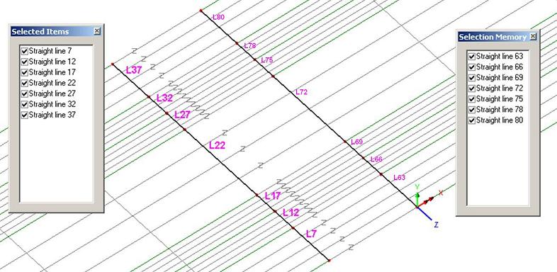
Joints assigned between
sets of selected lines
A
joint mesh can also be assigned to two sets of lines.
One set is selected and set in selection memory:
(right
click) [Graphics Window] > Selection Memory > Set
or
alternatively: Edit
menu > Selection Memory > Set
The
other set of lines is then selected in normal selection.
The joint mesh is then assigned. Selecting the option to
"Mesh from master to slave" will make the set of
lines in normal selection the 'Master' assignments to which joint
geometric and joint material attributes are assigned. The joint
mesh will be paired between the lines in selection and those in
selection memory. The pairing of lines is determined
either by the order in which they were selected (if selected by
picking), or in numerical order (if simply box selected). Diagram
illustrating the assignment
of joints between set of lines selected
Making
Features Unmergable
The features which have been generated must be made "unmergable", which means that when they share the same
coordinate positions they are not merged automatically by LUSAS
Modeller. You can do this by selecting the features and using the menu items:
Geometry > Point > Make unmergable
Geometry > Line > Make unmergable
Joint elements have no length in a stiffness matrix and so any length given in the model will introduce an inaccuracy in the length of any substructure features and will trigger a warning in
the LUSAS Solver text output file (*.OUT). However, moving the features at each end of joint elements to be coincident can make it difficult to be sure of the orientation of the joints element axes (local x, y, z). Therefore it is prudent always to use a local coordinate dataset to control the
axes, as described in the article on Mesh attributes
How do I model
lift off supports? (main page)
How
do I model tension only members? (main page)
How do I model a hinged connection between shell meshed
surfaces? (main page)
|
