User Area
Software Release History - Version 21
Version
21.1 | Version
21.0
New Facilities and Improvements
in LUSAS Version 21.0
V21.0-1 was made available for download on 19 February 2024
This is an error
fix release
V21.0-0 was made available for download on 27
November 2023
This is a major release
of new facilitites, enhancements and change requests. See below for
details.
In summary...
| Major
new facilities
Reinforced Concrete Slab /
Wall Design
Reinforcement
Vehicle Load Optimisation
Rail Track-Structure
Interaction enhancements
Bridge Deck (Grillage)
attributes
Section property
calculation
Staged construction
improvements
|
Geotechnical
Nonlinear solution settings
General modelling, analysis
and results improvements
LNG Tank System
Other
|
In detail...
New
Free Cantilever Method (FCM) Wizard
|
|
|
| Real-time
visualisation of tendons / stages |
Section
viewer |
- The FCM wizard creates the necessary
tendon loading attributes and assigns each to the correct segments
at each stage of construction, considerably speeding-up the
modelling process. Dynamic visualisation of tendons in the bridge
on plan, elevation and within each segment section is provided
within the wizard. On solving a model, tendon losses are
calculated to a chosen code of practice.
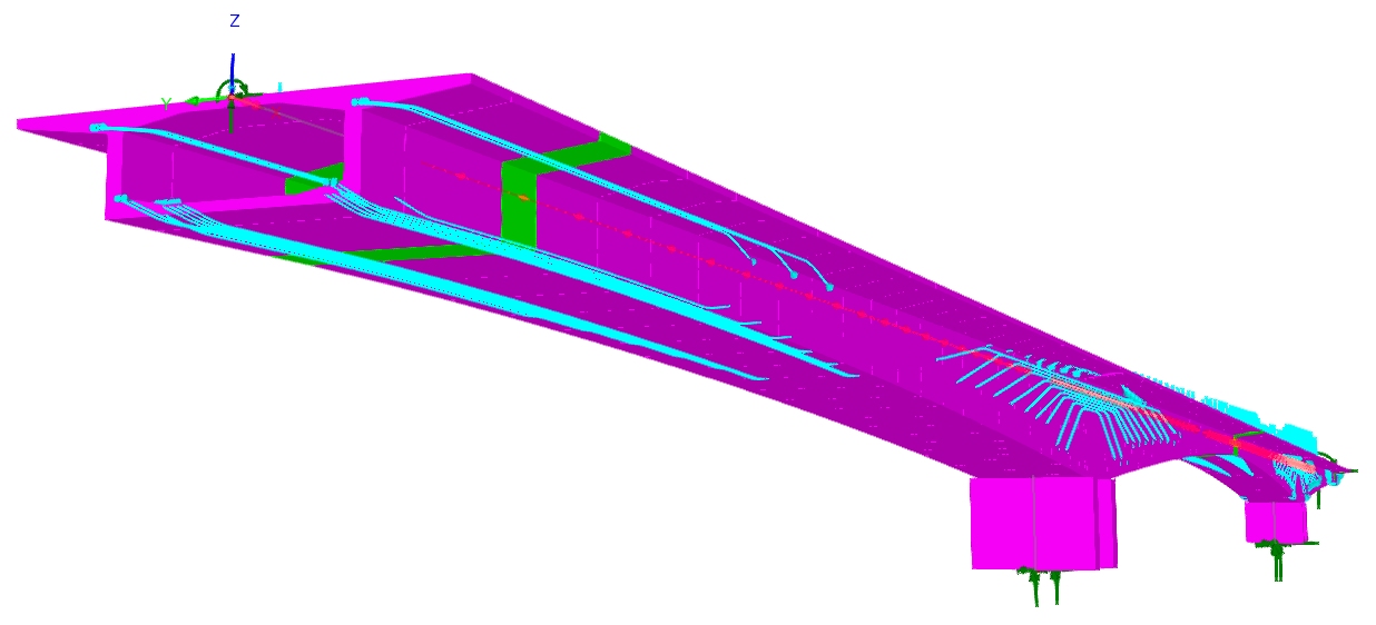 |
| Model
as built by the FCM wizard |
New Pedestrian Moving
Load Analysis
- The new Pedestrian Moving Load
Analysis facility is available for use with the step-by-step
dynamics option. It enables the dynamic effects associated with
pedestrians moving across a structure to be modelled in accordance
with a chosen design code, creating all the associated loadcases
for further evaluation. It requires a pedestrian load definition
(incorporating vertical pulsating and optional lateral and
longitudinal effects) that may be moved at a constant speed, along
a reference path, in a forward or reverse direction.
- A general pedestrian load may also
be defined and used to enter arbitrary constant and sinuisoidal
functions, define pedestrian loading for codes not currently
supported directly, and to apply the vertical component produced
by one code, but with a slightly different pedestrian speed than
the one enforced by that code's pedestrian load definition.
Moving Load
Analysis
- A new Moving Load Analysis facility
simplifies modelling of a vehicle load moving along a reference
path across a across a model of a bridge or an embankment. A
'Moving Load Analysis' entry is added to the Analyses Treeview,
containing a loadcase for each load position, along with maximum
and minimum envelope entries containing those loadcases to provide
the full effects of the load passing over the structure.
RC Slab/Wall
Design
- The RC Slab
/ Wall Design facility carries out comprehensive design checks
to more international Codes of Practice. It includes Strength/ULS
and SLS checks based on flexural, twisting and in-plane effects,
shear, stress limits, minimum and maximum areas of reinforcement
and crack widths or spacing considerations as appropriate for all
supported codes.
- The use of a sandwich model based
upon Annex LL of EN1992-2 (and CEB-FIP Model Code 1990) is now
provided for use with BS 5400-4:1990, BS 8007:1987 and BS
8110-1:1997 and BS8110-2:1985 (UK), IRS:CBC-1997 (India),
MOMRA Bridge Design (Saudi Arabia), NZS 3101-1:2006 and NZTA
Bridge Manual v3.3 (New Zealand), SABS 0100-1 (Ed. 2.2) (South
Africa) and SS CP65-1999 (Singapore). This major improvement to
the RC Slab/Wall design facility removes most of the limitations
of the previously implemented methods (Wood-Armer and
Clark-Nielsen) for those codes and extends the applications for
which this RC slab / wall design facility can be used.
- For the existing supported design
codes, which include those for USA, UK, India, New Zealand, Saudi
Arabia, Singapore and South Africa, shear design checks are now
included for BS 5400-4:1990, BS 8007:1987 and BS 8110-1:1997
and BS8110-2:1985 (UK), IRS:CBC-1997 (India), MOMRA Bridge
Design (Saudi Arabia), NZS 3101-1:2006 and NZTA Bridge Manual v3.3
(New Zealand), SS CP65-1999 (Singapore) and SABS 0100-1 (Ed. 2.2)
(South Africa).
- The 'Cope & Clark', 'Iterative
Cope & Clark' and 'Ignore Mxy and Nxy' methods of carrying out
calculations have been added to the 'General' tab of all supported
design codes for when principal axes do not align with
reinforcement directions.
- A new option added to the 'General'
tab of all design codes that provide a value for the calculation
of the cracking stress allows SLS checks to be based
conservatively on the assumption that all RC sections are cracked
- or less conservatively on the basis that below a specified
'cracking stress' threshold, sections may be assumed uncracked.
- Crack width calculations, for those
codes which include them, can now be calculated at the concrete
face or at the 'cover required for durability', giving additional
control over the design check to avoid over-conservatism.
- Detailed rendered calculations
referencing clauses from design codes are available for all checks
made for all design codes.
Easier modelling
of reinforcement in 2D and 3D continuum models
- Reinforcement bar arrangements can
now be modelled in 2D and 3D continuum models without the need to
subdivide the feature geometry to follow the lines of
reinforcement, greatly simplifying the modelling process. Lines
representing reinforcement bars are assigned parasitic bar
elements which sit wholly inside host elements. The node and
element spacing along the line to which the line mesh attribute is
assigned is determined by the intersection of the line and the
edges (2D/axisymmetric) or faces (3D) of the host elements through
which the line or lines pass. The line mesh created may also be
refined using spacing options.
 |
 |
| Surfaces
representing concrete and lines representing reinforcement bars |
Parasitic
bar elements created within host elements |
Typical application
- In this retaining wall example,
individual reinforcement bars are modelled in detail (allowing for lap
lengths where appropriate), grouped into a 'set' of bars and copied at
a regular spacing along the length of the wall. After solving,
stresses in bars can be readily obtained.
Vehicle Load
Optimisation
- A new Direct Method Influence Envelope
attribute has been introduced. These differ from Direct Method
Influence attributes in that they allow selection of all the
components that are to be optimised (as opposed to only being allowed
to only select one in the other Direct Method Influence attribute) and
they are assigned to meshed features and not directly to element
nodes. When assigned to point, line or surface features in a model
they will provide the optimised load effect of interest (e.g. My) at
all nodal locations in the assignment. If an option to include the
coincident effects is also chosen, all the coincident effects (e.g.
Fx, Fy, Fz, Mx, Mz) at all assigned locations will also be provided
for each selected results component (as opposed to having to select
which ones to include individually). The previous method, in which the
VLO facility generates load patterns each in a loadcase of its own, is
retained and is useful for checking purposes.
 |
 |
| Direct
Method Influence Envelope dialog |
VLO
Optional Loading Parameters dialog |
- A new rationalised placement method
option has been added to the VLO Optional loading and RLO Optional
loading parameters dialogs. This considers loading of adverse areas
only when placing a vehicle or train traffic load, ignoring the
relieving areas. Its use generally provides the most onerous vehicle
loading arrangements faster than by considering loading on all
loadable areas.
- In the Vehicle
Load Optimisation facility, traffic load effects can now be
obtained for the whole structure and not just selected locations of
interest. A new Vehicle Load Optimisation > VLO Envelope Run menu
item provides a faster alternative to having to use numerous
VLO-generated loadcases prior to solving the static analysis and then
enveloping those loadcases, as has been required previously. With the
new facility a single load envelope is created for each maximum and
minimum condition (i.e. for each Strength, Serviceability,
Characteristic or Frequent case, according to the selected Code of
Practice), for combining with other load cases as required. The
envelope is created for each DMIE (Direct Method Influence Envelope)
as well.
|
|
|
VLO Envelope
Run loadcases and associated printed results |
Rail Track-Structure
Interaction enhancements
- When carrying out Rail
Track-Structure-Interaction modelling in LUSAS, Zero
Longitudinal Resistance (ZLR) and/or Reduced Longitudinal
Resistance (RLR) properties and regions over which they apply can
now be considered. Use of these can help to relieve regions of
high axial stress in the tracks.
New and updated
Bridge Deck (Grillage) attributes
- The range of Bridge Deck (Grillage)
geometric attributes that are used to define the geometric properties
of specific bridge decks analysed with reference to, or derived from,
grillage formulae published by Hambly and others, has been extended
and enhanced. In addition to the existing Slab, Infill Slab, Girder
with Top Slab and Transverse Slab with Bracing attributes, options for
spaced box beams, multicellular slabs and shear key decks are now
provided.
Multicellular
 |
 |
| Multicellular
(longitudinal beams) |
Multicellular
(transverse beams) |
Shear key
 |
 |
| Shear
key (longitudinal beams) |
Shear
key (transverse beams) |
Girder and Top slab
- The
'Girder and Top slab' bridge deck geometric attribute
implemented in Version 20 has been extended to include tub
girders and precast U sections.
- Section types are now selected
via a droplist of bridge types, which sets the options available
for each beam type on each tab, and determines which formulae
are used for the calculation of properties.
|
|
Section property
calculation
- A tub girder section has been added to
the range of plate girder section property calculators. Top flange
bracing types can also be specified, allowing for easier modelling of
bridge decks incorporating these girders.
 |
 |
| Tub
girder section |
Tub
girder top flange (plan) bracing |
Staged
Construction improvements
- Material properties can now be
assigned to separate loadcases within a nonlinear analysis, rather
than be defined only for a nonlinear analysis as a whole. This
allows for easier solving of nonlinear problems with changing
material properties. There is no need to assign material to every
loadcase, only to the loadcase in which the material changes. When
a nonlinear analysis is solved, it will be assumed that the
material in a preceding loadcase is unchanged unless overwritten
by a new assignment. Assignment of a material now takes place in a
similar manner to that for assigning a support, where a feature is
selected and an analysis and loadcase are specified. Note that for
a linear analysis all material/composite assignments must be made
to the first loadcase of the analysis.
 |
 |
| Material
folder location prior to Version 21 |
Material
folder locations permissible in Version 21 |
- The Deactivate dialog has been
updated for ease of use. A new 'Fixed whilst deactivated' option
holds nodes in their as-drawn location, being released on
activation. This is useful when representing fill material or
concrete which is placed on site to an as-drawn level such as in
an embankment model. Deactivation may optionally be gradual over
the steps of an automatic nonlinear incrementation, rather than
occurring in one step. This assists with convergence when the
analysis also involves nonlinear materials or geometric
nonlinearity.
- A new Reset Deformation attribute
can be assigned to appropriate features in a model in order to
reset either node or element locations in order to establish an
initial equilibrium or other required state.
Geotechnical
enhancements
- Non-reflecting / absorbing boundary
supports can now be specified with viscous properties that
correspond to a continuation of the material at that boundary
continuing semi-infinitely beyond the support location.
- POP (Pre-Overburden Pressure) is a
new option to specify initial stress state in the Duncan-Chang and
Modified Mohr-Coulomb models.
- Groundwater solution controls have
been added to the nonlinear control Advanced Solution Strategy
dialog.
- New options for drainage/filling
curves are included when a partially saturated material is
defined. These are: 'Constant water content', 'Valiantzas', 'Van
Genuchten-Mualem', 'Brooks-Corey' and 'Piecewise linear'.
- Pore water pressures can now be
defined directly, or indirectly by defining phreatic surfaces
(which represent the position of the free water surface) along
with soil properties and boundary conditions.
- Concentrated, face pressure and
global distributed loading definition dialogs now allow for the
input of pore pressure fluxes (m3/s for concentrated loads, m/s
for others) for elements that support this capability.
- Normal and tangential stiffnesses
for the Mohr-Coulomb Friction Interface material can be input
either as factors (as already available) or as absolute values.
- A new Water Pressure Distribution
loading attribute is introduced. The pressure profile may be
calculated either from a phreatic surface or from fully defined
profiles that are assigned to the continuum.
- The new water pressure distribution
loading and phreatic surface attributes can be used in various
ways to specify or determine pore water pressure throughout the
soil block (continuum).
 |
 |
Note that geotechnical modelling
facilities are only available for licence keys that support that
option.
Nonlinear solution
settings - changes to dialogs
- The advanced nonlinear
incrementation parameters dialog has been made easier to use and
also sees the introduction of a new 'Path direction' option for
arc-length control.
- The nonlinear advanced solution
dialog has been made easier to use and also sees the introduction
of a new line search strategy option for iterative acceleration..
- The advanced time step parameters
dialog of the Time Domain panel of the Nonlinear & Transient
control dialog has been simplified.
- Arc-length restart parameters have
been moved from the Advanced Nonlinear Incrementation Parameters
dialog to the Initial State tab of the Analysis dialog.
General modelling,
analysis and results improvements
Interfacing with Revit
- An 'Export to LUSAS' plugin for Revit
will be made available from the Autodesk App Store at https://apps.autodesk.com/en
- Using the plugin, Revit
analytical model information can be exported to create a
corresponding LUSAS model or a LUSAS Visual Basic script for
importing. Revit �analytical elements� are converted to
appropriate LUSAS features and finite elements, along with
cross-sections and material attributes, and the conversion of
loads and supports.
Improved display
of values, labels and general model annotation
- Results values on the Values and
Diagrams layers and text labels and annotation are now, by
default, only displayed if they do not clash with other values,
labels or text visible in the model view window. In situations
where clashes occur, higher results values take priority over
lower ones and larger negative values take priority over lesser
ones, with clashing values or text made transparent, providing
clearer displays.
- Values are now displayed with a
location symbol to show where they relate to on a model.
- Enlarging the view of a model will
progressively make previously clashing text visible.
|
|
|
| Values
plot showing only main values |
Enlarged
view showing all values |
 |
| Diagram
plot showing only main values |
 |
| Enlarged
view showing all values |
Beam projected
loading (wind)
- A new loading attribute 'Beam Projected
Loading (Wind)' has been introduced allowing you to assign a pressure
loading to line beam members to model wind loading. It can accommodate
complex variations of pressure with height or other variables. Loading
is evaluated on each member to which it is assigned on the basis of
the area (i.e. the length x section width) that member presents in the
plane perpendicular to the pressure loading.
 |
 |
 |
 |
 |
| Constant |
Linear |
Parabolic |
Stepped
with cut-offs |
Profile
variation |
Beam end releases
now support partial fixity
- Partial fixity of the ends of a
member represented as a line or a combined line may be specified
for a chosen freedom as either a factor or a spring stiffness
value.
Dimension lines
- A new 'Dimension Lines' attribute
has been introduced, providing 'distance' dimensions aligned to
global directions or aligned to the member (to give the 'true'
length), and 'ordinates' as an alternative. Colours, fonts,
arrowheads, decimal places and units may be controlled for each
view window in the Attributes layer of the Layers treeview.
 |
 |
| Distance
dimension types |
Ordinate
dimension types |
Design reports
improved
- LUSAS design reports, which show
design calculations with clause references have been improved:
Reporting facilities have been made more consistent across the
range of LUSAS design facilities (RC Slab / Wall Design, RC Frame
Design, Composite Deck Design, Steel Frame Design etc). Any
selected rendered design checks may be added to a LUSAS report,
and all the rendered design check reports may be printed
consistently.
- Reports can now be searched for
particular text and one or all of the rendered design check
reports within the currently open dialog may be saved in
searchable PDF format.
- Interactive rendering checks are now
carried out concurrently.
- Formatting of long equations has
been improved. For example. if an equation 'stack' will fit into a
page width they are shown with any equals signs aligned in case of
a multiline equation, and if an equation does not fit the page, it
will be split at appropriate locations into a multiline entry.
 |
| Improved
equation formatting in LUSAS design reports |
Concrete modelling
- For concrete heat of hydration
modelling, advanced exothermic property "correction
factors" have been added to an Advanced dialog. These make it
possible to adjust specific entries to better match experimental
results.
Python scripting language
supported
- Session files and other script files
in Modeller can now be optionally written out in Python as an
alternative to VBScript. Modeller already executes Python scripts
or commands entered in the LPI command bar, and so this makes it
easier to create such scripts. This requires Python and 'Python
for Win32 (pywin32) extensions (2022)' to be independently
installed. See 'Modeller Settings' in the LUSAS Configuration
Utility for more details.
Speedups
- Results are now assembled faster
when viewing contours, values, diagrams, Print Results Wizard
output and similar.
- The Vehicle Load Optimisation and
Rail Load Optimisation facilities now rapidly produce envelopes of
traffic loading effects over sections or the whole of the model
(without producing many loadcases) and use a rationalised method
to generate these results - or load patterns, if selected - more
rapidly.
- Results processing of both IMD
loadcases of element results that utilise the 'Spectral' results
option with the 'CQC Combination' spectral response type and IMD
loadcases of element results for large models is now substantially
faster.
- The time taken to draw fleshed
members and contours has been greatly reduced and memory demands
have been lowered, enabling the creation of much larger, more
detailed beam models when using standard sections.
- The rendering of selected members
within the model view has been optimised, leading to significantly
faster response times for interactive selection in large models.
- The 'Combination and envelope
settings' object in the Analyses Treeview has been replaced with a
new object named 'Results cache'. The results cache item provides
continuous feedback, within its name, of the amount of disk space
currently used by the cache. Caching of results is now turned on
by default and will make second and subsequent requests of results
faster.
- Auto renumbering of Nodes and
Elements, and Point, Line, Surface and Volume geometry is now set
'off' by default. If models created in previous versions have it
turned on, Modeller's performance for larger models can be
improved by turning it off.
- Locking of a model during editing
enables interactive work with larger models to be speedier.
- Some mesh checks that have been
found to be unnecessary are switched off by default but can be
enabled from the Advanced Meshing Parameters dialog.
New graphic drivers
supported
- LUSAS now offers more rendering
options, including DirectX, to support a wider variety of modern
graphics cards, providing a most robust interface, especially on
machines where up-to-date graphics drivers are not always available.
Improved
rendering of models
- Model visualisation has been improved
with the addition of new model view illumination options. These
include global lighting, which broadly mimics sunlight, and point
lighting, which mimics isolated sources of light such as streetlamps.
For global lighting the location and direction of the incoming global
light, its movement in relation with the eye position of the scene,
its magnitude and colour, and whether ambient occlusion should be
applied can be defined. For local lighting each light source's
position, colour, brightness, and whether ray marched shadows are
applied can be stated.
- Model view backgrounds and ground
planes are now supported. View backgrounds can be a solid colour, a
static image loaded from disk, or a chosen predefined skybox that
comprises a set of 6 images that form the top, bottom and four sides
of a cube that encompasses the view of a model to give the illusion of
a vast, open 3D background. Ground planes help to visually locate or
'ground' a model in 3D space and include 'Graph paper', 'Chessboard'
and 'Solid colour' options and a range of 'texture' styles.
 |
| Perspective view of model with a ground plane, a skybox and a light source |
Modification
watermarks and visual reminders when results are out of date
- A "Modification Mode"
watermark will now appear in the upper half of a model view window
when the model has been modified more recently than solved. In
addition a "Results are out of date" watermark is
displayed in the lower half of a model view window to emphasise
this point.
- When viewing Print Results Wizard
output, for a report or a graph that was created with 'out of
date' results, a message stating that the values are 'out of date'
is printed above the data. These measures are intended to ensure
that users are aware that the viewed or printed results are not
those that would necessarily be obtained if the model was solved
again.
- If a model is loaded into Modeller
and an associated results file from Solver is found to be 'out of
date', you will no longer be asked if you want these results to be
loaded, and instead will have to load them manually - saving time
waiting for out of date results to load.
These notifications and changes will
allow you to continue to view results while altering a model, and also
ensure that you are reminded of the need for the model to be re-solved
to obtain updated results.
Locking of model during
editing
- A new menu item Tools > Mesh >
Attribute Evaluation Lock has been added to prevent LUSAS Modeller
from evaluating the effect of any change (creation, modification,
assignment) to most attributes. This is similar to locking any
evaluation of changes made to the mesh using the 'Mesh lock' menu
item and can be used to work faster with larger models.
- The existing Mesh lock button has
been modified to become a drop menu, with the new Attribute
Evaluation Lock option added to it.
- When the Mesh layer is being
displayed and the Mesh Lock is 'on', the Mesh layer image (for all
views) now changes to include a padlock to show that the effect of
any changes made will not be seen on the model until the lock is
turned 'off'.
- When the Attributes layer is being
displayed and the Attribute Evaluation Lock is 'on', the
Attributes layer image (for all views) will change to include a
padlock to show that the effect of any changes made to any
attributes or their assignments will not be seen on the model
until the lock is turned 'off'.
Other enhancements
- From Version 21 onwards, surfaces
created in a 2D analysis ((inplane, axisymmetric and grillage) are
automatically reversed if necessary, so that the surface normal
aligns to the global Z axis. Existing models and scripts are not
affected by this change. The existing surface reverse command is
unaffected, so it is still possible to manually control the
surface normal in all analysis types. If the analysis category is
changed from 2D to 3D or vice versa the surface normals do not
change.
- A number of mesh checking parameters
have been added to the Advanced Meshing Parameters dialog.
- References to "master" and
"slave" in situations where both normally appear
together (such as slidelines) have been renamed to be
"primary" and "secondary". Any other
references to "master", which denotes a controlling
feature or capability without a subservient one, have been
retained.
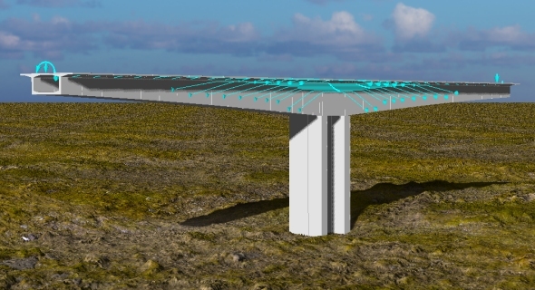
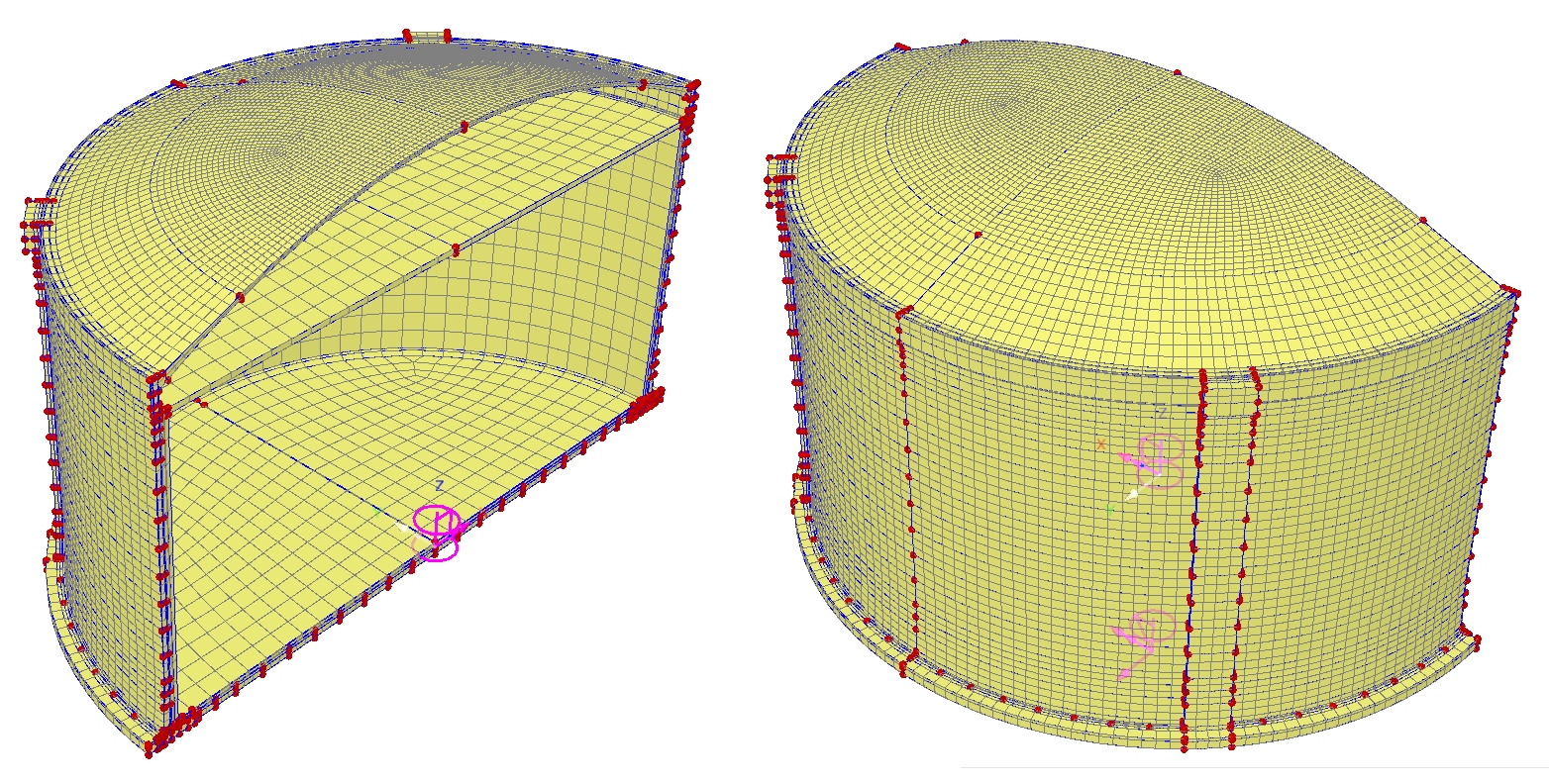
LNG Tank System
The LNG�Tank System that allows engineers to automatically create a range of 2D and 3D finite element models of full containment circular tanks from user-defined parameters, now supports:
- Double walled steel tanks.
- Solid models of concrete tanks with buttresses. These are coupled structural � thermal, full, half or quarter sized models, with explicitly modelled wall reinforcement, ringbeam reinforcement and spillage scenarios.
User change requests
The originators of all requested
changes to the software that have been incorporated in this release
will be notified individually.
Documentation
User manuals
- All online and printable
documentation has been updated for this new release.
- Selected manuals are provided in PDF
format as part of the LUSAS installation and are also available
for download from the LUSAS website.
Worked Examples
- Worked examples (in PDF format) and associated files referenced by
those examples are available for download from the User Area of
the LUSAS
website.
|