User Area
> Advice
Using joints between faces of surface features
Using Joints: Mesh
| Geometric
attributes | Material
attributes | Spring
stiffnesses | Supports
| Loadcase properties
The joint elements must be assigned between two surface features
(these are designated "master" and "slave"). These
surface features must be part of the model, e.g.
having a support attribute assigned, or being one face of a volume meshed with continuum
elements. The joint material
will then define the behaviour of the joints between the two.
Note that for simple lift-off/contact
supports it is easier and often sufficient (for either a linear
or nonlinear analysis) to simply by choose the
"Lift-off" option for a particular freedom in a defined
support attribute.
Attributes menu > Support...
> (click) "Lift-off >>"
For more advanced or complex
contact/lift-off problems, or where the mating faces have
dissimilar mesh, the use of Slidelines may be more suitable.
Please see
Help > Help Topics >
Contents > Chapter 5 - Model Attributes > Other Attributes
> Slidelines
Joints between faces of volume features
 You must have a model which includes two
volume features (or a volume feature and a supported surface feature parallel to one
face)
arranged such that you can assign the joints between two
parallel surface features. You may need to temporarily create a
gap between the two surfaces (e.g. copy a volume feature at an appropriate
offset and delete the original volume). You must have a model which includes two
volume features (or a volume feature and a supported surface feature parallel to one
face)
arranged such that you can assign the joints between two
parallel surface features. You may need to temporarily create a
gap between the two surfaces (e.g. copy a volume feature at an appropriate
offset and delete the original volume).
Diagram
illustrating the features required
The features which have been generated must be made "unmergable".
Joints assigned to surfaces where
a shell mesh is also required
 Between
a shell mesh and a support Between
a shell mesh and a support
Strictly
speaking, a feature can only have one mesh assignment.
However, if a feature has a mesh already assigned, but is also
required to be an assignment for a joint mesh attribute, then this
feature can be made the 'Slave' assignment for the joint mesh,
whilst maintaining its original mesh assignment also. Where
modelling a meshed surface with lift off supports for example, a
copy of the initial surface would be made and this new surface is supported. The
new supported surface could then be designated as
the 'Master' assignment. The joint surface mesh then assigned
between this (Master) new surface and the initial meshed (Slave) surface.
Diagram
illustrating the surface features required
The features which have been generated must be made "unmergable".
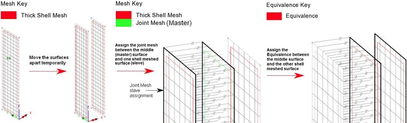
Between two parallel shell meshed surfaces
A different scenario which may be
required is where a
joint mesh is meshed between two parallel shell meshed surfaces. If two coincident shell meshed surfaces with matching mesh pattern are to be modelled as connected or contacting using joint elements for example, they should first be moved a distance apart whilst assigning the joint mesh for practical reasons. An additional surface is required between the two to take the joint mesh master assignment and then one of the shell meshed surfaces will be the slave assignment, leaving the other with no joint mesh assignment at all. Then an
Equivalence attribute is created (Attributes menu >
Equivalence) with the default tolerance set. This is assigned to the middle surface and the shell meshed surface that is not assigned as the slave assignment surface. Then ensure that the two equivalenced surfaces (and its underlying lines and points) are set as
unmergable and then all three surfaces can be moved back to be coincident.
|
|
Diagram
illustrating the three surface features required and joint and
equivalence assignments
Please see the following help topic for more information regarding
Equivalence:
Help > Help Topics >
Contents > Chapter 5 - Model Attributes > Other Attributes
> Equivalence
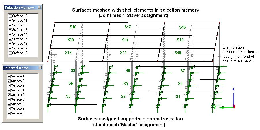
Joints assigned
between sets of selected surfaces
A
joint mesh can also be assigned to two sets of surfaces.
One set is selected and set in selection memory:
(right
click) [Graphics Window] > Selection Memory > Set
or
alternatively: Edit
menu > Selection Memory > Set
The
other set of surfaces is then selected in normal selection.
The joint mesh is then assigned. Selecting the option
to "Mesh from master to slave" will make the set
of surfaces in normal selection the 'Master' assignments to which
joint geometric and joint material attributes are assigned.
The joint mesh will be paired between the surfaces in selection
and those in selection memory. The pairing of surfaces is determined
either by the order in which they were selected (if selected by
picking), or in numerical order (if simply box selected).
Diagram
illustrating the assignment
of joints between set of surfaces selected
Making
Features Unmergable
The features which have been generated must be made "unmergable", which means that when they share the same coordinate positions they are not merged automatically by LUSAS
Modeller. You can do this by selecting the features and using the menu items:
Geometry menu
> Point > Make unmergable
Geometry menu
> Line > Make unmergable
Geometry menu
> Surface > Make unmergable
Joint elements have no length in a stiffness matrix and so any length given in the model will introduce an inaccuracy in the length of any substructure features and will trigger a warning in
the LUSAS Solver text output file (*.OUT). However, moving the features at each end of joint elements to be coincident can make it difficult to be sure of the orientation of the joints element axes (local x, y, z). Therefore it is prudent always to use a local coordinate dataset to control the
axes, as described in the article on Mesh attributes.
How do I model
lift off supports? (main page)
How
do I model tension only members? (main page)
How
do I model a hinged connection between shell meshed surfaces? (main
page)
|
