User Area > Advice
Isoparametric Finite Element Analysis Formulation
The
isoparametric formulation of finite elements is recognised as being most effective in
practical analyses, having the following advantages
-
It readily allows the coordinates and displacements at any point within an element to be found using an assumed displacement and coordinate variation
-
Different element shapes and numbers of nodes are easily generated
-
Material and geometric properties may vary over an element and are properly accounted for by use of appropriate values at the element Gauss Points
The
isoparametric formulation uses the following two relationships
·
{u} = [N}{d}
Where:
{u} are the displacements at any point within an element
{d} are the displacements at the nodes of an element
This relates the displacements at any point within an element to
the nodal displacements according to an assumed displacement variation ([N])
·
{x} = [N}{X}
Where:
{x}
are the coordinates of any point within an element
{X}
are the coordinates of the nodes of an element
This
relates the coordinates at any point within an element to the nodal coordinates according
to an assumed displacement variation ([N])
The matrix [N] is known as the shape function
or interpolation matrix and is a function of the natural
coordinate system used. It is used in equations (1)
and (2) to determine the variation of both the coordinates
and the displacements within an element. That is, for a
geometrically well-defined element shape, the shape function
matrix establishes a unique relationship between the displacements
and coordinates at any point within an element with those
at the nodal positions.
As an example, consider how the stiffness matrix of a 3-noded bar element
is generated with the isoparametric formulation. This element
has an axial degree of freedom at each node only and a natural
coordinate system based on x is used as follows

By the use of a
quadratically varying shape function assumption the element can exactly model a
quadratically varying displacement (and coordinate) field. Such a variation is given as

If the strains
are calculated as

From the
relationship {u} = [N]{d}, we have

Where
[B] defines the “strain-displacement” matrix as

However
it has been previously seen that [N] is specified in terms of x rather than x. Therefore, using the chain rule, this may be written as

Giving

The
term  is
worthy of closer inspection since it turns out to be of significance in the finite element
method. Using {x} = [N]{X}, we have is
worthy of closer inspection since it turns out to be of significance in the finite element
method. Using {x} = [N]{X}, we have


If x2 is (reasonably) assumed the midpoint, then x2 = x1+L/2
and x3 = x1+L, so that

Reducing
to

Mathematically, dx/dx
represents a “scale factor” between the two coordinate
systems and is commonly termed the Jacobian.
This is an important association and is commonly denoted
as [J], so that, for this 3-noded bar example

In this case [J] is a simple value for the length of
the bar, although in general, it will be a matrix with a
dependency on the natural
coordinate system.
The
strain-displacement matrix defined above is then given by

And
the strain as

Indicating
that, although a quadratic shape function will simulate a quadratic displacement
distribution across an element, the strain (and, therefore, stress) will actually vary
linearly. Similarly a linear shape function will lead to constant strain values within an
element. For more information on shape functions click here.
The
element stiffness matrix is defined as

Where
[D] is called the “modulus” or “material stiffness” matrix and, in the
case of the bar element, is defined as

Where E is the elastic modulus for the material. Normally
the stiffness matrix would be evaluated using numerical
integration. For now the solution is obtained analytically
as follows

Since


When,
when expanded, gives

After
multiplication of the separate matrix terms, we have

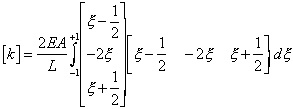
Integrating
with respect to x gives

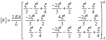
And
evaluating over the natural coordinate limits of ±1, yields

Which,
after simplification, gives the element stiffness matrix as

To
check that this stiffness matrix produces the expected structural response, consider the
3-noded bar (diagram at beginning of this page) of cross sectional area (A) =1, elastic
modulus (E) = 100 and length (L) = 10, axially supported at node 1 and subjected to a
concentrated axial load of 5 at node 3. If the displacements at nodes 1, 2 and 3 are d1,
d2 and d3 respectively, the element displacement vector becomes

Where
d1 is set to zero as a result of the applied support condition. The element
force vector specifies the applied load at node 3 together with the reaction force (R1)
at the supported node 1 as

Given
the static equilibrium equation

This
gives

Extracting
the three equations as


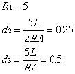
Solving
for d2, d3 and R1 gives

As
expected.
Finite
Element Theory Contents
Local
Coordinate System
Shape
Functions
Numerical
Integration
The
Jacobian Matrix
|