User Area
Software Release History - Version 14
Index
| Version
14.7 | Version
14.6 | Version
14.5 | Version
14.4 | Version 14.3 | Version 14.2 |
Version
14.1 | Version
14.0
New
Facilities and Improvements in Version 14.7
Overview
- Mesh-only modelling
- Cursor selection filters for
selection of mesh objects
- Gravity loading as a property of
a structural loadcase
- Display of beneficial and adverse
load factors
- Contouring of joint results
- Improved force/moment diagram
labelling (released in V14.7-4)
- Updated Traffic Load Optimsation
facility for changes to EN1991-2 for Sweden (released in V14.7-9)
Mesh-only modelling
A new File > Import
Mesh menu item allows mesh-only models to built in LUSAS by
importing finite element data files created either by the prior
running of an analysis in LUSAS or, more usually and beneficially, by
importing data files from other supported software applications to
carry-out checking of analysis results using LUSAS. Files currently
supported include Abaqus input files, Ansys cdb files, and Nastran
bulk data files.
Mesh-only models
differ from the normal feature-based geometry models in LUSAS in that
they are comprised of nodes and elements and do not contain any
geometric feature types, or indeed any geometric data at all. During
the mesh import process, LUSAS Modeller creates separate Groups for
each element type encountered and for models created from LUSAS data
file these will be familiar LUSAS element names. For models created
from other third-party software they will be the names used within
that system, whatever they may be. An option to create additional
groups based upon the element material type is also available.
No import of any
attribute data is done when element data is imported, so the mesh
objects (the elements and their nodes, edges and faces) must be
assigned attributes (materials, properties and thicknesses, loading
and supports), prior to carrying out an analysis within LUSAS, in a
similar way and as documented for a feature-based geometry model.
Rather than selecting points, lines, surfaces or volumes to make an
attribute assignment, the nodes, edges and faces of elements as well
as the elements themselves can be selected instead.
Cursor selection filters for selection
of mesh objects
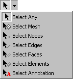 Cursor
selection filters now differ according to the model type in use. The
existing geometry-based selection cursors remain unchanged but a new
cursor menu is displayed for mesh-only models. Cursor
selection filters now differ according to the model type in use. The
existing geometry-based selection cursors remain unchanged but a new
cursor menu is displayed for mesh-only models.
For mesh-only models
the ordinary selection cursor (Select Any) will select only Nodes,
Elements or Annotation. In addition
to nodes and elements, element edges and element faces can now also be
selected. The complete list of cursor selection filters (showing
keyboard shortcuts) is as shown:
M
– Mesh selection filter
N
– Node selection filter
B
– Edge selection filter
F
– Face selection filter
E
– Element selection filter
A
– Annotation selection filter
Gravity loading as a property of a
structural loadcase
As an alternative to
defining gravity by specifying and assigning a constant body force to
all features in a model, or by using the Bridge > Bridge loading
> Gravity menu item, it can now be optionally be added to a model
as a property of a structural loadcase. As a result of this new
functionality, the applying of gravity loading to staged construction
modelling problems with numerous loadcases is greatly simplified.
Defining gravity
loading as a property of a loadcase can be done in three ways:
- By
selecting the the Automatically add gravity to this loadcase
option on the dialog that is displayed when defining a new
loadcase or displayed when editing the properties of an existing
loadcase.
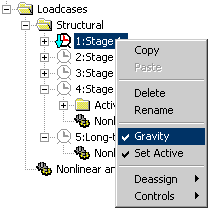
- By
selecting the Gravity menu item from the context menu for
an individual loadcase.
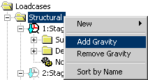
- By
selecting the Add Gravity menu item from the context menu
of the Structural folder in the Loadcase Treeview. This
effectively sets gravity loading to be 'on' for all structural
loadcases in the Treeview regardless of whether they previously
had gravity loading added or not. For the special case of
loadcases having nonlinear controls, gravity loading is only added
to those loadcases defined with Manual incrementation and not to
loadcases defined with Automatic incrementation because the latter
inherit the properties of the preceding defined Manual increment
 |
 |
|
Specifying
gravity for a single loadcase
|
Specifying
gravity for all loadcases
|
Gravity loading is defined in
accordance with the vertical axis direction that was specified either
initially on the New Model dialog or subsequently on the Vertical Axis
dialog accessed using the Utilities > Vertical Axis menu
item. No visualisation of gravity loading on the model is provided for
gravity defined as a property of a loadcase. However, the general
loadcase icon will change to include a loading arrow symbol  to show that gravity is included for a particular loadcase.
The worked example Staged
Construction of a Concrete Tower with Creep has been updated to
illustrate use of gravity loading as a property of a loadcase.
Display of beneficial and adverse
Load Factors
The Combination and Envelope Results
dialog associated with the  Combination
and envelope options object contains a new option to
display beneficial/adverse factors in smart combinations. This
switches the smart combination labels on the smart combination dialog
and associated grid dialog from Permanent/Variable to
Beneficial/Adverse. Combination
and envelope options object contains a new option to
display beneficial/adverse factors in smart combinations. This
switches the smart combination labels on the smart combination dialog
and associated grid dialog from Permanent/Variable to
Beneficial/Adverse.
Contouring of joint results
It is now possible to contour joint
results. This is done by selecting the Stress - joints menu item in
the contour dialog. Joints are drawn as coloured circles that
correspond to the values shown in the contour key. The size of the
circles drawn is set by the 'pen width' edit box on the contours
display settings.
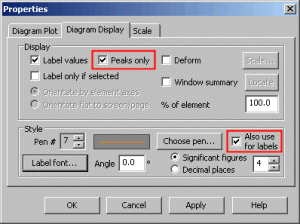 Improved
force/moment diagram labelling (released in V14.7-4) Improved
force/moment diagram labelling (released in V14.7-4)
Improvements to force/moment diagram
labelling include a new default option on the Diagram Properties
dialog to enable peak values only to be displayed.
An option is also provided to allow
diagram values to be a different chosen colour from the diagram
itself.
Other minor changes concern default
settings:
- The default font size has been
changed from 10 to 11
- The default magnitude has been
changed from 6mm to 10mm
- The default number of significant
figures has been changed from 6 to 4.
Updated Traffic Load Optimsation
facility for Sweden EN-1991 (released in V14.7-9)
Traffic Load Optimisation facility has
been updated to comply with changes made by Trafikverket (the Swedish
Transport Administration). A choice can now be made between EN1991-2 Sweden (2009) or EN1991-2 Sweden (2011).
Changes cover the addition of two new fixed axle prototype vehicles: (m) and (n) from Appendix 3 of TRVFS2011:12 [T1]
and a reduction in the default dynamic allowance to 20%.
 User
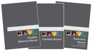
Manuals User
Manuals
All relevant
documentation has been updated for this new release and is provided in
PDF format as part of any V14.7 software download file or on the V14.7
software CD. Changes have been made to the following manuals:
Changes to Worked Examples
All examples have
been reviewed and updated as required for this release. Of particular
note are:
- Staged
Construction of a Concrete Tower with Creep:
updated to illustrate use of gravity loading as a property of a
loadcase
Potential issues for Windows 7 users
opening PDF files referenced in CHM files
At the time of
releasing the on-line help files for Version 14.7 it appears that some
users on Windows 7 machines with IE9 installed may not be able to open
the PDF files that are linked in the Contents panel of the LUSAS
Modeller Online Help. "Microsoft HTML Help executable has
stopped working" is reported when a PDF manual is clicked in the
Contents panel.
If problems
are found in opening these files in this way please note the
following:
- Uninstalling
IE9 and re-installing IE8 has been found to allow the PDF files
to be opened successfully from the Contents panel.
- Other
workarounds/solutions may be provided by Microsoft during the
availability and support of this particular LUSAS software
release.
- All manuals
are supplied in PDF format on the installation kit and these are
normally installed into the <LUSAS Installation Folder>
/Programs/PDF_Manuals folder.
Retired elements and facilities
|