User Area
Software Release History - Version 14
Index
| Version
14.7 | Version
14.6 | Version
14.5 | Version
14.4 | Version 14.3 | Version 14.2 |
Version
14.1 | Version
14.0
Improvements and New Facilities
in Version 14.2
New products : LUSAS
LT versions
 LUSAS
Bridge LT and LUSAS Civil & Structural LT software products are
now available. LUSAS LT versions have a reduced set of menu options
and simplified dialogs containing only those features and options
required for linear static analysis of 2D/3D frames and grillages.
These
new
versions allow for rapid prototyping and provide an effective way of
servicing a variety of analysis and design requirements whilst
requiring a minimum of training of engineers on a single system. LUSAS
Bridge LT and LUSAS Civil & Structural LT software products are
now available. LUSAS LT versions have a reduced set of menu options
and simplified dialogs containing only those features and options
required for linear static analysis of 2D/3D frames and grillages.
These
new
versions allow for rapid prototyping and provide an effective way of
servicing a variety of analysis and design requirements whilst
requiring a minimum of training of engineers on a single system.
- LT versions can operate alongside other LUSAS software products on the same
network with different numbers of users to suit project needs.
-
Models created in LT can be opened in Standard and Plus versions if
more advanced analysis is required to be carried out.
- Models and
results files created in other LUSAS products can be edited and
viewed in LT versions provided the model contains only those
elements supported by LUSAS LT.
 New
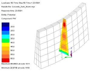
product option: Heat of hydration analysis New
product option: Heat of hydration analysis
A software option for modelling the
heat of hydration of concrete is now provided. The heat of concrete
hydration can be computed during a thermo-mechanical coupled
analysis and the temperatures and degree of hydration can be read
into a structural analysis.
A new example involving staged
construction modelling and analysis of a dam is provided to
illustrate the use of this new facility.
New facility:
Plotting of stress results on beams
 Beam stresses can now be plotted on
beams as opposed to having to calculate and plot stress resultants
on beams as in previous releases, and contours of both beam stresses
and stress resultants can now be plotted on deformed or undeformed
fleshed beam cross-sections. Beam stresses can now be plotted on
beams as opposed to having to calculate and plot stress resultants
on beams as in previous releases, and contours of both beam stresses
and stress resultants can now be plotted on deformed or undeformed
fleshed beam cross-sections.
These new facilities allow for plotting
just line contours on top of fleshed beams; mixing fleshed contours
on beams with bar contours; or plotting full solid contour fleshing
with lines and labels.
A new concept of �fibre locations� is
used to define the positions on a beam section at which stress
results should be calculated and diagrams plotted.
Supplied standard
section library components include pre-defined fibre locations at
the extreme positions for all sections.
 New
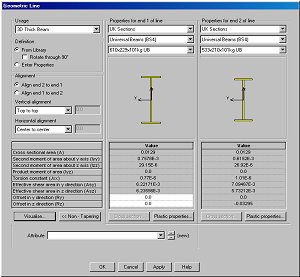
facility: Creating varying beam cross-sections New
facility: Creating varying beam cross-sections
Creating tapering beams is now much
simpler. Selecting the Attributes > Geometric > Line menu
item now displays an all-inclusive Geometric Properties dialog that
allows for definition of beam properties by selecting a beam type
from a section library location, or by manually entering properties.
-
A Tapering option lets you specify properties for each end of the beam.
- Beam
alignment options allow for specifying vertical and horizontal
alignments of one end from an other and for offsetting the beam ends
(defining an eccentricity) from a nodal position.
Model and results displays
Changes made to the way that the
OPENGL system is used by LUSAS Modeller now give faster display
speeds and faster dynamic rotation of large models.
A configuration
utility allows you to choose whether Hardware or Microsoft software
OpenGL drivers are used. This is in addition to the hardware
acceleration choices that are available from the troubleshooting
pages of the advanced display properties in Windows that allow you
to manually control the level of hardware acceleration and
performance of your graphics hardware.
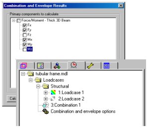 Combinations
and envelopes Combinations
and envelopes
Load combinations and envelopes can
now be defined at the time of building a model as well as when
results processing. As a result, when the first combination or
envelope is created for a model a new Combinations and envelopes
options object is added to the loadcase Treeview. Double clicking on
this entry displays a dialog that allows specification of which
combination and enveloped component results should be calculated
automatically straight after the model has been solved.
Combination
and envelope results created in this manner are saved (cached) in a
new Modeller Results File (.mrs). This means that results do not
have to be calculated for the same results component every time a
combination or envelope is set active (as was done in previous
versions) and this helps to provide faster display of contour and results
plots.
New facility:
Multiple automatic influence creation
 Changes have been made to the way in
which influence attributes are defined for use with influence
analysis. A new menu command Attributes > Influence
creates an influence definition as an assignable attribute, rather
than a utility item, and, as a result, influence definitions now
appear in the Attributes Treeview for assigning to your model data
using the standard drag and drop technique. On the model, more than
one influence point can be chosen at any one time and the influence
attribute can be assigned to all at once. There is no need to
manually select break-away elements, instead LUSAS now automatically
determines the break-away elements to be used. Influence point
visualisation is now switched �on� by default and can be
displayed as nodes and arrows indicating the direction of break-away
elements or by nodes and symbols representing the same thing. If
mesh spacing is changed following the definition of influence points
all defined influence points are retained in the Treeview. Influence
points that still coincide with nodal points are graphically
highlighted as such in the Utilities Treeview and others that no
longer sit over nodal points are also identified but with a
different 'unassigned' symbol. Unused influence points can be
deleted if required, or, if left, and the mesh spacing is
subsequently changed again resulting in coincident influence points
and nodes again they will be highlighted as such in the Treeview. Changes have been made to the way in
which influence attributes are defined for use with influence
analysis. A new menu command Attributes > Influence
creates an influence definition as an assignable attribute, rather
than a utility item, and, as a result, influence definitions now
appear in the Attributes Treeview for assigning to your model data
using the standard drag and drop technique. On the model, more than
one influence point can be chosen at any one time and the influence
attribute can be assigned to all at once. There is no need to
manually select break-away elements, instead LUSAS now automatically
determines the break-away elements to be used. Influence point
visualisation is now switched �on� by default and can be
displayed as nodes and arrows indicating the direction of break-away
elements or by nodes and symbols representing the same thing. If
mesh spacing is changed following the definition of influence points
all defined influence points are retained in the Treeview. Influence
points that still coincide with nodal points are graphically
highlighted as such in the Utilities Treeview and others that no
longer sit over nodal points are also identified but with a
different 'unassigned' symbol. Unused influence points can be
deleted if required, or, if left, and the mesh spacing is
subsequently changed again resulting in coincident influence points
and nodes again they will be highlighted as such in the Treeview.
 New
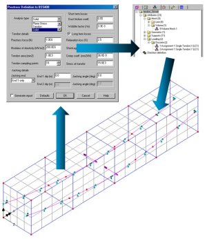
facility: Tendon loading for 3D solid models New
facility: Tendon loading for 3D solid models
The Single Tendon Prestress Wizard
now includes a Solid analysis type option. With this option discrete
loading values are calculated for a selected tendon (that must be
defined as a spline) and are then applied to the solid mesh elements
in the model as equivalent nodal loads.
- A LUSAS model may contain
many tendons and the single tendon prestress wizard can be used
separately on each to derive equivalent nodal loading on the mesh
for all the tendons used.
- The lines representing the tendon are not
included in the final analysis model.
- Tendon alignment / realignment
is, very usefully, independent of the underlying mesh arrangement.
Generic creep /
shrinkage enhancements
3D CEB-FIP and creep has been
implemented in 2D, 3D continuum elements, shells, continuum
composite elements, and in beam elements that support quadrilateral
cross-sections.
The uniaxial Chinese Creep law has been implemented
for all elements supported by the CEB-FIP creep law. In the Chinese
creep law, shrinkage and swelling are not considered but this
implementation of shrinkage in LUSAS will allow CEB-FIP shrinkage to
be combined with the Chinese creep law if necessary to satisfy the
requirements for the creep analysis of 3D structures like dams.
New joint models
The existing range of joint models
has been extended to include a number of seismic isolator joints.
Viscous dampers, lead rubber bearings and friction pendulum systems
can now be modelled.
 New installation
wizard and easier network licensing New installation
wizard and easier network licensing
A new installation wizard simplifies
the installation of LUSAS and the loading of subsequent updates. It
also simplifies installation of network licence software and allows
for a mix of any number and type of licences to be used.
An enhanced
LUSAS configuration utility allows for easy licence key input and
licence type detection.
LUSAS also now supports mixed licence
types on a network licence.
Faster model
displays
Changes made to the way that the
OPENGL system is used by LUSAS Modeller now give faster display
speeds and faster dynamic rotation of large models.
 Easier
manipulation of models Easier
manipulation of models
The way that a model is dynamically
rotated has been changed to use the 'model ball' method. With this
method, a model can be imagined to be surrounded by a sphere such
that a mouse-click and a drag of the cursor on the screen represents
clicking on the surface of the sphere and dragging to rotate it to a
new position. In doing so, it is important to note that the model
rotation is restrained to rotate only around the model's vertical
axis (as defined on the Vertical Axis dialog) - unless any model
viewing shortcuts are being used at the same time. The main benefit of this
approach is that, no matter where on the screen you click to start
the rotation of your model, if you return the mouse pointer to the
same spot, (whilst you are dynamically rotating the model), the
model will return to its original position and orientation on the
screen.
Rotation, zoom and pan model
manipulations are now applicable to all cursor input modes. This
means that, for example, with the correct mouse button clicks, lines
can be drawn from one point to another whilst dynamically panning,
zooming or rotating the model.
 View
/ Model axis View
/ Model axis
The view / model axis has been
re-styled and colour-coded.
 New facility: User-Defined
Startup Templates New facility: User-Defined
Startup Templates
It is now possible to create customised startup templates by recording a sequence of commands such as setting default mesh divisions, materials, preferred screen colours etc. and saving them in an automatically generated VB script for re-use when using the New Model dialog.
Memory Enhancements
Version 14.2 includes extended
virtual memory settings for Modeller and Solver first made available
for use in V14.1-2.
Country-specific
enhancements
|
Precast library extended
The following United States and
Canadian precast beams are available for selection from the precast
beam section generator:
 AASHTO Type II - VI beams
Florida Bulb T72, T78 beams
 NU Girders
|
Section library extended
The following steel sections have
been added to the standard section library:
 Australian steel sections
Canadian steel sections |
|
Material libary enhancements
The following materials have been
added to the supplied material library:
Canadian concrete properties
 Chinese concrete properties
|
Additional Vehicle Loadings
 Poland vehicle loadings for K-Class A to E and S-Class A to E
vehicles are now supplied.
Poland vehicle loadings for K-Class A to E and S-Class A to E
vehicles are now supplied.
|
Chinese language
version of LUSAS
Version 14.2-2 sees the release of a
Chinese language version of LUSAS. Language type can be selected
during the installation procedure or by running the LUSAS
Configuration Utility, selecting the language option required,
closing the utility and re-running LUSAS. The appropriate Windows
Regional and Language Settings must be selected and installed for
correct running of the software.
|
