Software Option for
Plus versions
Heat of Hydration
The Heat of Hydration software option
allows for modelling the heat of hydration of concrete for a variety
of cement types. Effects due to the addition of fly ash and ground
granulated blast furnace slag can also be included. When used with the Nonlinear, Dynamic,
and Thermal software options the heat of concrete hydration can be
computed during a thermo-mechanical coupled analysis, with the
temperatures and degree of hydration used by a structural analysis to
determine a range of time and age-dependent effects.
In summary
LUSAS has long been
known for its advanced analysis capabilities, with a concrete cracking
and crushing material model developed over many years in collaboration
with top researchers in the field. Using the time-dependent creep and
shrinkage concrete material model allows for better assessment of
existing concrete structures and better predictions for concrete
placed quickly or adjacent to existing material.
For early age concrete, hygro-thermal
analyses allow the determination of heat of hydration across a body of
concrete, taking into account the availability of water for the
exothermic reaction with time, based on the concrete mix, shape,
exposed faces, insulated surfaces, environmental conditions etc. This
avoids the use of "typical" heat generation curves, although
these can still be drawn upon for comparison purposes.
When a hygro-thermal analysis is
coupled with a structural or "mechanical" analysis, the
cracking, crushing, creep and shrinkage capabilities of LUSAS can be
employed.This allows the determination of time- and age-dependent
deformations, stresses, crack-widths and more, working to - and beyond
the scope of - international Codes of Practice.
In detail
The Heat of Hydration
software option allows for 2D/3D modelling of coupled
thermal-mechanical behaviour of concrete due to its curing, and can
also allow for inclusion of formwork and other materials that might
act as insulators. The analysis results in thermally induced strains
that can be used to calculate crack widths and crack patterns. Heat of
Hydration analysis can be undertaken on mass or reinforced concrete
with detailed geometric modelling of reinforcement within the concrete
section being possible. The user has full control over the ambient and
casting temperatures at the start of the analysis and can also allow
for fluctuations in temperature. The internal inclusions of artificial
cooling or heating can be done at discrete locations in a 2D analysis
or along pipe lines in a 3D analysis. Results from LUSAS have been
validated against academic research and also against a third party
heat of hydration program.
|
Heat of hydration example
In the simplistic example shown
right, a cube of concrete is modelled with an 8x8x8 mesh of
HF8/HX8 elements and the concrete curing process is simulated.
Temperatures due to the heat of hydration can be obtained by
examining the hourly timestep results.
From the half-model results it
can be seen that the greatest temperature differential occurs at
34 hours.
A structural analysis using a
concrete cracking model based upon mechanical properties for
this time interval is then carried out and cracks can be
observed when differential expansion is enough to cause
principal stresses that lead to material failure.
|
|
|
Animation of
temperature change in mid-section of concrete block |
|
|
|
|
Crack planes at 35
hours |
Maximum principal
stresses at 35 hours |
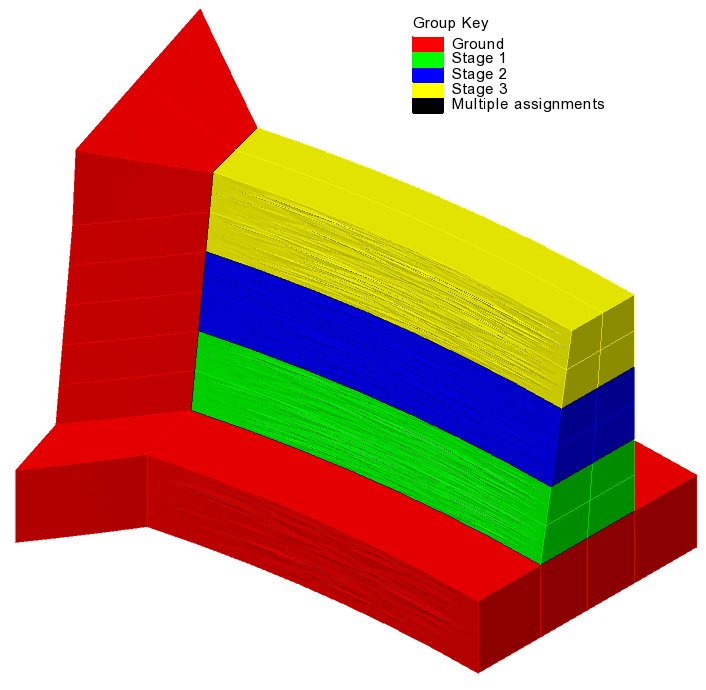
Hygro-thermal analysis of a dam
For the
staged construction of a dam, the effects that formwork and
environmental conditions have on the curing concrete can be examined
and The temperatures and stresses for each
time step for each construction stage can be obtained.:
|
|
|
| Staged
construction model |
Modelling
formwork during a stage |
|
|
|
| Temperature |
Stress |
|
|
Graphs of results such as the changing
of concrete temperature over time, shrinkage and thermal strains, or
water distribution, and more can be obtained:
And calculated crack widths for each
time step in each construction stage, both internally and externally,
can be visualised:
Dependent software options
Use of the Heat of Hydration software option
requires the following other software options to be accessible.
Find out more
|