Case Study
Faster Vibration
Analysis of Automotive Exhaust Systems
Mechanical vibrations of vehicle exhaust systems can cause both cabin
noise and structural durability concerns. To reduce the time taken to assess new exhaust
systems Arvin Exhaust R&D, based in Warton, England commissioned FEA Ltd's consultancy
department to produce the Arvin Modal Analysis Program (AMAP) as an extension to LUSAS Analyst
which already in use. By using AMAP the vibrational behaviour of proposed new exhaust
systems can be evaluated more rapidly than by manual modelling or other previous automated
methods giving man-time reductions of around 50%.
Because dynamics modelling requires highly idealised representations of
complex sub-assemblies, a different approach is required to that used for component level
analysis meaning that direct transfer of full 3D CAD models is not useful. Instead, a
partially automated 'top down' approach is adopted, where AMAP provides a strict framework
for model creation and verification, analysis set-up and post-processing. This imposes
discipline and consistency on the analysis process. In addition, for dynamic analyses of
this type it is essential that the complete exhaust assembly is modelled - including a
representation of the engine and manifold. This is because dynamic excitation is
predominantly comprised of unbalanced forces within the engine, and forced vibration
response calculations are only possible if the vibration source is included in the model.
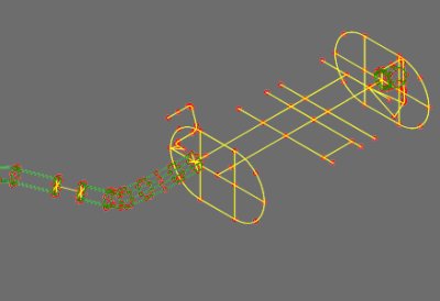
To model
an exhaust system the coordinates of all pipe and muffler centrelines are defined, either
by using forms within AMAP or by importing centreline data from a CADDS V model, via an
intermediate ASCII file. Once done, individual sections of centreline which make up a pipe
run or muffler can be selected graphically with AMAP providing a form to allow tube
diameter, thickness and bend radius to be entered.
Muffler boxes are located in a similar manner to pipe
runs. Because these components can be very complex internally with the configuration being
application-specific, and with the degree of structural connection between baffles, tubes,
end plates and casing varying considerably with either "lock-seam" or "clam
shell" construction, less automatic modelling procedures are used. However,
significant modelling aids are still provided by AMAP. On-screen forms are used to define
muffler tube or baffle size, perforation pattern, packing density, end plate details etc.
Connections between muffler components are modelled using springs, so that flexible,
articulated or sliding connections can be defined. Definition of these springs is assisted
by a very useful "exploded view" facility, which separates the muffler
components on the screen so that springs may be inserted graphically. AMAP automatically
defines and assigns all mass and stiffness property data to the model based on data
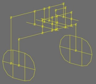
entered by the designer. 'Trace lines', another useful feature, are provided to indicate
outlines of muffler and converter boxes where a 'wire-frame' as opposed to a 'shell model'
idealisation is used.
In addition to pipe runs and mufflers, catalytic converters, exhaust
manifolds; rigid-mass representations of engine/transmission assemblies including
compliant mounts and exhaust system hangers can be individually defined and added to the
model. In transversely mounted engines a "hinge" between the engine and exhaust
system is also required to de-couple "torque wind" movements of the engine. Both
knuckle and bellows type de-couplers have a marked effect on the dynamic response of the
exhaust system, and so careful modelling is required. Beam elements with axial, bending
and shear flexibility are used to represent bellows type connections, with spring elements
being used for knuckle joints.
Careful checking is especially important for dynamic analysis models.
Incorrect representation of mass or stiffness is likely to have more influence on dynamic
response predictions than a similar error in a static analysis. Considerable effort was
made in the development of AMAP to assist the task of checking the model. Throughout the
creation of the model, AMAP tracks and controls numbering of property data, so that when
the model is complete an annotated table of properties can be requested. The program also
creates plots showing properties assigned to all the features in the model. The table and
plots together form a complete description of the model, allowing comprehensive checking.
Further checking data is provided by the LUSAS analysis run, which lists total mass and
centre of gravity of all materials in the model. Since each component is assigned a
different material, masses of individual mufflers etc. can be readily checked.
LUSAS
provides a number of different eigensolvers for natural frequency analysis. AMAP
automatically selects the solver that has been proved most effective for exhaust system
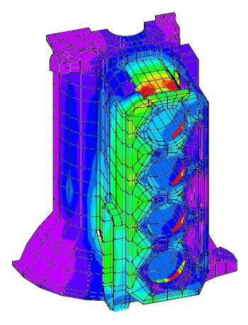
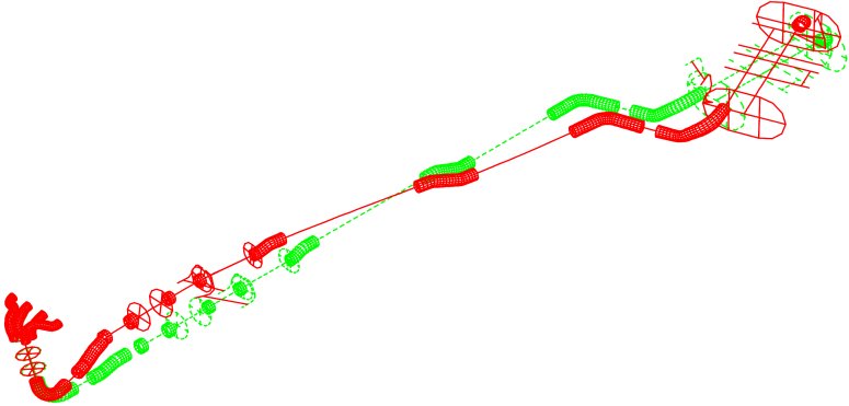
models. Once the eigenvalue analysis has been performed, AMAP produces a complete set of
annotated mode shape plots. On-screen mode shape animations are also generated for
interactive viewing. LUSAS results processing features include tools for interactive
dynamic response calculation, using previously calculated mass normalised eigenmodes. This
facility is invoked by AMAP to automatically generate frequency response functions for
critical response positions, such as chassis attachment points.
For modal analysis it is very important that the analytical model
represents the true behaviour of the physical system under investigation. To achieve this,
Arvin Exhaust use LMS modal test software to measure and extract mode shapes and
frequencies of selected prototype systems for comparison with AMAP/LUSAS predictions. The
LUSAS-test correlation process is assisted by the LMS-export facility within the LUSAS
results processing features which provides mesh and mode shape data in CADA-X format. Many
of the modelling techniques and rules in AMAP evolved as a result of LUSAS-test
correlation, and it is expected that this process will continue for the foreseeable
future.
"Our evaluation of proposed new exhaust systems can
now be performed at least twice as fast as previous methods with greater accuracy also
being achieved."
Ian Rutherford, CAE Team Leader,
Arvin Exhaust R&D
Other LUSAS Analyst case
studies:
|