Case Study
The design and analysis of a laser mirror assembly
A High Energy Laser facility designed at the
Atomic Weapons
Establishment provides tools for advanced materials research. Engineers at AWE
used LUSAS Analyst to help optimise the design of a laser mirror assembly used at the
facility.
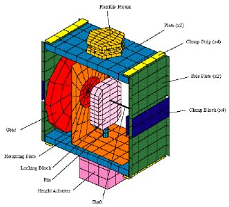
Mirror assembly details
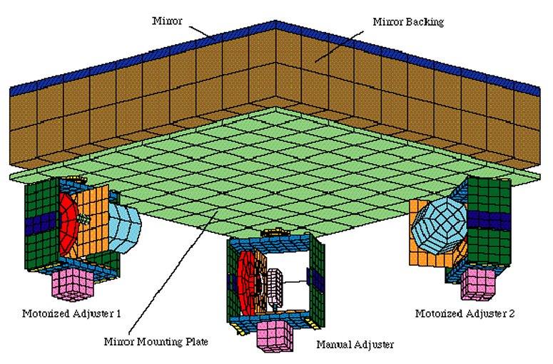
Each computer controlled mirror assembly directs a 400mm x 400mm laser beam onto the
target area. The mirror itself must remain flat and stable during use to achieve a
pointing accuracy of 50�m at the target end of the 250m long beam path. To achieve this,
each 425mm x 425mm x 10mm thick quartz mirror is bonded to a 70mm thick block of syntactic
ceramic foam (Patent application number GB9701519.2) and attached to a mounting plate.
Three height adjusters, fixed to the 70,000 tonne concrete structure of the laser
facility, support the mounting plate via 3 flexi cross hinges which are mounted at optimum
support positions.
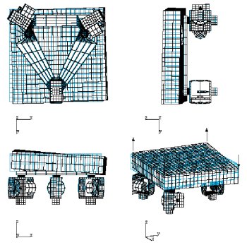
All components of the mirror assembly were modelled
separately and attached together using a total of 84 sets of
slidelines. Slidelines allow
separate non-matching meshes to be used on contacting surfaces. With
slidelines,
remodelling or moving of components without extensive remeshing is possible and interface
conditions can be easily altered to suit design changes. In all, 61 total model components
of 10 different materials were defined resulting in a total model size of 4000 elements.
Design considerations
The pitching modes of vibration were of primary concern in this analysis since these would
affect the accuracy of the laser beam at the target the most. Heave, sway and torsional
modes would have no effect on the target accuracy. The design aim for the lowest frequency
mode was set at 10Hz. A series of analyses were carried out to investigate possible
enhancements to an initial mirror assembly model.
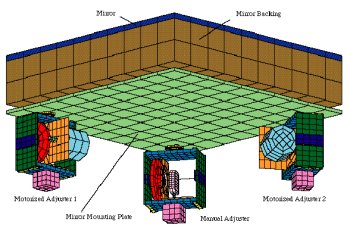
Initial Mirror Model
A natural frequency analysis of the initial mirror model found the lowest vibration mode
to be a torsional one at 23.2Hz with the second mode being a pitching mode of 29.9 Hz.
Investigations into adjusting the angle of the side plates, stiffening the mounting plate,
and re-orientating the height adjusters resulted in raising the pitching and torsional
modes.
|
|
|
| Initial
mirror assembly |
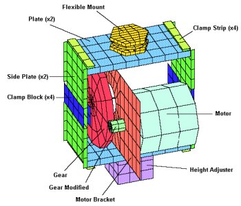
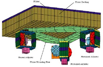
Final
mirror assembly |
Modified Mirror Model
Based upon the initial findings the mirror mounting plate was then redesigned to increase
stiffness and reduce mass. The height adjusters were also repositioned. As a result, a
modal analysis of the modified design significantly increased the lowest natural frequency
to 76.7Hz with no significant pitching modes occuring below 160Hz. With this model a
loading analysis with the motorised height adjusters set to maximum adjustment of +/-
0.75mm and 1g vertical acceleration was carried out to investigate the effect on the
mirror flatness. The target maximum design normal deflection was set by the laser
engineers at 0.25�m. By investigating reducing the mounting plate thickness and mirror
backing and flexi hinge properties a revised final mirror assembly design was achieved.
|
Final Mirror Model
The final design of the Mirror Assembly was found to have lowest pitching modes of 50.6Hz
and 54.2Hz - well above the target minimum. The frequencies dropped from the optimum
because of the reduction in Mounting Plate stiffness and the modifications to the flexi
cross hinges. The final mirror assembly model was analysed to determine the response
characteristics of the mirror surface when subjected to a ground excitation of 1E-10g/Hz
over a range of 1 to 200Hz in all three orthogonal directions. The normal Power Spectral
Density displacement response of the mirror surface was calculated for the surface nodes
using LUSAS Graphics and the resulting deflections plotted.
Conclusions
By using LUSAS Analyst the design of the surface flatness of the mirror was
improved significantly by providing optimum adjuster assembly locations and orientations,
increasing the overall stiffness, reducing the overall weight and decreasing the effect of
adjustment. Estimates of expected deformation patterns and their magnitude have helped the
laser engineers understand and improve their design. The models and techniques used in
this analysis will provide AWE with a basis for further development of the laser mirror
assemblies and to provide analysis guidelines for other similar equipment.
|
|
|
� Crown Copyright
|
|
Other LUSAS Analyst case
studies:
|