Case Study
Fatigue
Analysis of Tubular Joints with Single-Sided Welds
MSL Engineering, a leading UK Engineering Consultancy specialising in
advanced analysis, assessment, repair, R&D, audit, verification and reliability
evaluations for the offshore industry used LUSAS to investigate the stress distributions
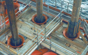
in typical offshore K joints formed from single-sided welds. K joints are a popular leg
configuration for North Sea structures and consist of two brace members welded to an
existing section (the chord) in a K configuration. It is usually the welds that are of
concern because of their potential for failure by fatigue.
Construction of tubular joints in North Sea Platforms has typically
relied on access to the inside of the brace to either dress or complete a full penetration
weld. However, it has been recognised that welding of tubular joints from the outside
only, represents a cost-effective construction method; this technique results in tubular
joints with single-sided welds. It has also been recognised that single-sided welding
represents the only real option for retrofitting new brace members in existing offshore
installations. Additional bracing may be required in a number of instances, including
replacement of damaged braces or upgrading of the installation to support extra topsides
facilities
With double-sided welds, the weld quality on the inside and outside is
similar and the controlling site for fatigue is typically on the outside because the
combination of notch stresses and stress concentration factor (SCF) here is greater. With
single-sided welds, potential root defects contribute to a lower quality of weld on the
inside. Consequently, unless the SCF on the outside is significantly greater than that on
the inside, potential fatigue problems may originate on the inside where they are far more
difficult to detect. Therefore, the design problem is one of determining the SCF at both
the inside and the outside and determining which site contols fatigue life.
The schedule for this project was tight, so MSL’s engineers for the
project worked with one of FEA’s consulting engineers for a number of days to enable
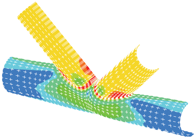
the FE models to be rapidly created. Initially, MSL used the LUSAS pre and post-processor
to perform the geometric modelling of the braces and chord. This required use of advanced
facilities in LUSAS for modelling the intersection of the cylinders and the weld itself
coupled with manual interaction to establish the final mesh details.
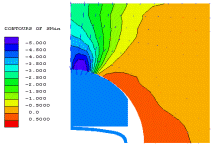
The project was conducted in two stages. The first involved validation
to ensure that the FE strategy, type of element and the mesh density were appropriate to
give accurate results. This encompassed modelling the geometry of one particular
configuration of K joint for which experimental data had previously been obtained using
strain gauges. The validation analysis indicated that using only one layer of the 20-noded
brick elements to model the chord and braces gave sufficient accuracy.
The second stage was to investigate how various geometric parameters of
K joints, such as ratios of brace-to-chord diameter, chord diameter-to-thickness, affect
SCF’s. After careful evaluation of the analysis results obtained from
LUSAS, MSL
observed that a near-linear relationship existed between some of the geometric parameters
and SCF ratios. In the future, the results from these investigations will be used to
assist in fatigue evaluations of offshore structures which contain tubular joints formed
with single-sided welds.
Other LUSAS Analyst case
studies:
|