Case Study
Stress
and thermal analysis of an LNG marine loading arm
Transferring Liquid Natural Gas (LNG)
from shore to ship and vice-versa at a temperature of -163 degrees
Celsius presents a number of problems due to thermal shock and ice
build-up on the transfer equipment. To help assess the behaviour of
a new LNG loading arm design during cool-down, operation and
subsequent warm-up Woodfield
Systems Ltd (now part of Aker
Solutions) employed LUSAS Consultancy Services. By using
LUSAS Analyst it was possible to prove to the client Abu
Dhabi Gas Liquefaction Co. Ltd (ADGAS) that its request for halving
the cool-down period could be achieved without any detrimental
effect on key components.
|
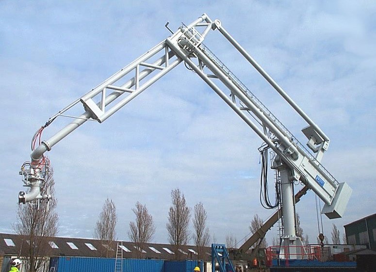
Overview
The 16 inch nominal diameter
loading arm is a new design to replace existing LNG loading arms
at the ADGAS Das Island Site in the United Arab Emirates. It
consists of a base riser contained within a pedestal fixed to the
jetty and a system of articulated pipes attached to a
counterbalance supporting structure. Swivel joints allow for
movement of the arm in all planes and freely follow the motion of
any tanker when connected. These joints are required to carry high
loads and must not allow any product leakage. Before LNG can be transferred the
loading arm components must undergo a cooling process to prevent
thermal shock. Nitrogen and/or LNG vapour is pumped through the
system initially, before LNG is introduced. To fully investigate the effect of
this cooling process a number of different analyses have been
carried out including Steady-state Thermal, Steady-state
Semi-coupled Thermo-mechanical, and Transient Semi-coupled
Thermo-mechanical using four separate and very detailed finite
element models.
Loading arm
assembly
A 3D model of the whole pipeline
assembly modelled the global behaviour of the system. This highly
complex modelling and analysis process simultaneously analysed the
effect of thermal and structural loads on the product flow-line.
Results obtained confirmed the amount of shrinkage and stresses in
the components as a result of the cooling and highlighted the
importance of using localised models for more detailed analysis.
|
|
|
Jetty
pedestal
A 3D model of the pedestal,
top-box, riser, swivels and luff and slew bearings investigated
the cooling effects of the riser pipe on surrounding components. A
conservative steady state thermal analysis was used due to the
convection and conduction effects involved.
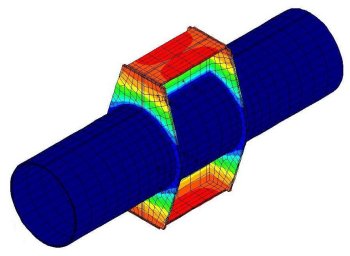
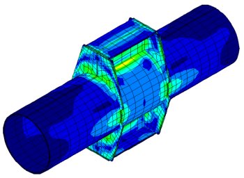
Support
brackets
A 3D model of a support bracket
investigated the extent of cooling and thermal stresses induced as
a result of the relatively rigid circumferential restraint. Whilst
less prone to suffer from thermal shock (as the plates are thin)
the brackets were susceptible to developing a thermal gradient
caused by the plates acting as warming fins on the pipe. As a
result the brackets were subject to further design and modelling
to improve their performance.
|
|
 |
|
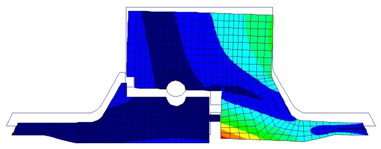
Swivels
A 2D axisymmetric model of a swivel
joint investigated its performance under a variety of transient
thermal loadings. Thermal loadings give temperature profiles and
thermal stresses that vary in time. As a result, graphs of time
temperature histories and plots of von-Mises equivalent stresses
and relative axial displacements for selected nodes on the swivel
easily showed the different stages of the cooling regimes
considered and helped assess whether the seals could maintain
product sealing during cool-down and loading.
Reducing
cooling-down time
The 2D transient thermal analysis
of the swivel showed that the male part cooled much quicker that
the female part due to their relative masses and configuration. To
evaluate different cooling options maximum von-Mises Equivalent
stresses on the most highly stressed part of the swivel were
plotted for comparison and are shown on the accompanying graph.
Red Curve
: An analysis assuming the introduction of LNG liquid with no
prior cool-down period shows why prior cooling is necessary.
Stresses exceed the allowable for the material chosen.
Blue Curve
: A cool-down period of 2 hours (as used on the existing installed
loading arms) using a mixture of nitrogen and LNG vapours produces
the least stress on the swivel when pure LNG is introduced.
Green
Curve : An investigative 1 hour cool-down period of 15
min Nitrogen/LNG mix followed by 45 min LNG vapour cools the
system faster than the the 2 hour regime. However, this causes a
corresponding increase in stress levels resulting in the peak
level at the introduction of LNG being approximately 20% higher.
Pink Curve
: A 1 hour cool-down using only LNG vapour produces the most
favourable result. The system cools faster and whilst the stresses
are the highest initially, the peak stress at the introduction of
LNG is only slightly higher than that caused by the 2 hour regime.
This is the recommended option.
Benefits
By employing LUSAS as an
independent consultant Woodfield Systems were not only able to
confirm or adjust their designs to ensure that they met the best
possible design conditions but were also able to provide complete
confidence to their client that the designs used would provide
trouble free operation, improve vessel turn-around and give
longevity of service.
Other LUSAS Analyst case
studies:
|