Case Study
Automated dynamic analysis of high speed drill spindles
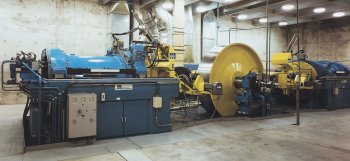
Systematic Drill Head are a worldwide supplier of bespoke drill heads
and precision spindles, primarily to engine manufacturers in the automotive industry. To
help speed-up application-specific tooling designs the company purchased LUSAS finite
element software, and instructed FEA Ltd's Engineering Consultancy Services department to
develop a customised user interface for automated vibration analysis.
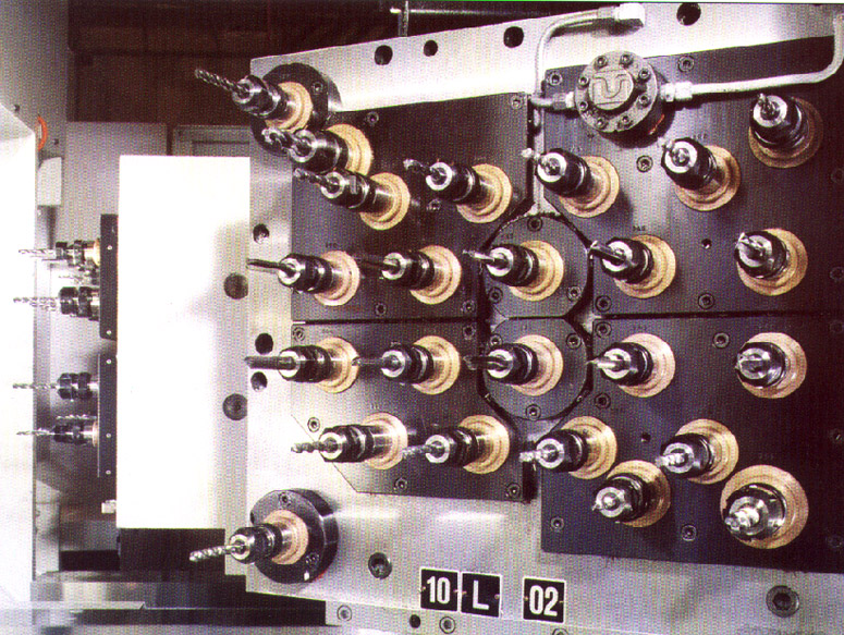
Vibration performance is a critically important factor in the machining
process of drill spindles. Even very small amplitude vibrations, or "chatter",
can lead to unacceptable surface finish on machined parts. In extreme cases, vibration can
cause failure of the tool or workpiece. Avoidance of resonance problems is therefore an
important factor in the design of machining systems. Since prototype testing is not
usually possible within the development cycle, vibration considerations must be resolved
at the design stage.
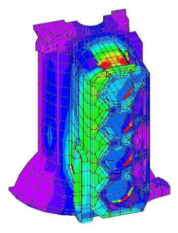
Preliminary investigations suggested that simple line beam models were
capable of providing acceptable dynamic solutions, and these form the basis of the
"parametric" program. 3D beams represent the drill spindle, with bearings
represented by spring supports. An eigenvalue analysis is performed to determine natural
frequencies and mode shapes for the spindle, including in-plane and out-of-plane bending,
axial and torsion effects. Interactive Modal Dynamics (IMD) procedures are used to
calculate frequency response functions, which are compared to the spindle running speed
and its harmonics. The complete process is automated to the point where the user is only
required to describe the shaft profile and bearing arrangements. All meshing, analysis and
post-processing (including dynamic forced response) is handled by the program, with
minimal user intervention. Apart from accelerating the analysis process, this approach
imparts consistency to modelling and analysis operations.
Since the spindle models were relatively simple, a straightforward
"top down" approach was adopted for model construction. The user enters the
outside diameter, internal diameter and length for each section in turn, starting from one
end and working along the shaft assembly to the other end. As well as constructing the
line beam model that will be used for the structural analysis, the program generates a
series of surfaces to indicate the actual geometry entered. Also, non-structural
"light stiff" crosses of beams are added to the structural model at section
changes, to aid visualisation in post-processing. (Without them, torsion modes would be
especially hard to identify.) All geometric and material properties are automatically
calculated and assigned as the program proceeds.
Once the shaft is defined, axial position designation and pre-load of
bearings is entered. The line beam model is automatically broken at the bearing positions
and springs are added. A database of bearing stiffness is scanned, and user-input of
stiffness requested if an unknown bearing designation is selected. Once the finite element
idealisation is completed, the user is prompted for the number of modes required, and
LUSAS results files are automatically generated for both static and eigenvalue analysis.
Automated post processing functions include static stiffness output, animated modeshape
display and frequency response generation.
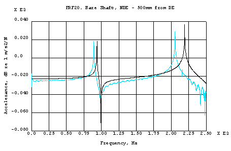
| Wherever
possible, dynamic analysis methods should be validated by comparison with test results. In
this case, a dynamic test of a typical spindle was performed, with frequency response
measurements of both the bare shaft and the assembled spindle. An instrumented impact
hammer and accelerometer were used, along with "Data Physics" PC-based 2-channel
FFT analysis equipment to capture and process force and response signals. This test
provided a series of high quality frequency response measurements of a 2,500 Hz band. A
typical comparison between measured and predicted frequency responses is shown on the
accompanying graph. |
 |
FEA's Engineering Consultancy Services successfully customised LUSAS to
perform rapid automated dynamic analysis of drill spindle assemblies. Results have been
validated by comparison with test measurements, with acceptable correlation achieved. The
delivered solution can be used effectively by practising design engineers with minimal
specialist expertise.
Other LUSAS Analyst case
studies:
|
|
Software Information
|