Case Study
Glass
Reinforced Plastic (GRP) and Aluminium Bolted T-joints
The UK's National Physical Laboratory
(NPL) used LUSAS Composite
to undertake a parametric study of two types of bolted T-joints
under various static loading conditions. The effect of varying
section properties such as web and base plate thicknesses, flange
radii and bolt positions was investigated for both yield and fatigue
assessments and for verification with laboratory testing. This
on-going work forms part of the Measurements for Material Systems
(MMS) Programme funded by the UK's Department of Trade and Industry.
|
Overview
Bolted T-joints have a variety of
mechanical, civil, aerospace and marine applications where they
are expected to sustain static or cyclic fatigue loads for
considerable periods of time with no adverse effect on their load
bearing capacities. However, under dynamic fluctuating or constant
loads, joints have sometimes been seen to fail at stress levels
much lower than the strength of the joint under static loading. To
address this issue NPL is investigating which parameters are of
direct concern when designing a bolted T-Joint. The eventual aim
is to produce a working guide stating the importance of those
parameters with respect to general joint performance.
|
|
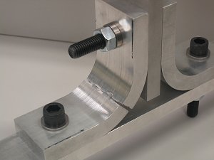
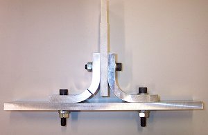
Bolted T-Joint
Types
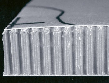
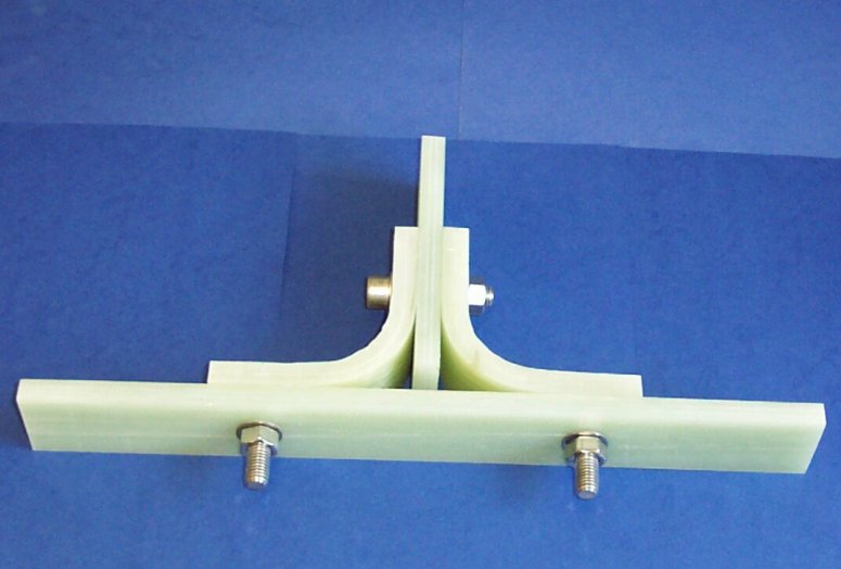
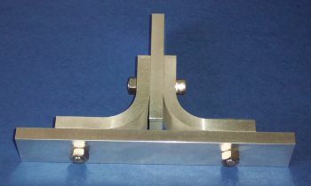
Glass Reinforced Plastic (GRP) and
aluminium bolted joints were chosen for investigation. Both were
of similar make-up, differing only in their nominal thickness. The
GRP joint components consisted of a combination of 0.64mm thick
unidirectional plies and 0.4mm thick biaxial woven plies to make
up a nominal 12.16mm plate thickness. Aluminium joints were 15mm
thick and of 2014-T6 aluminium alloy. In both cases a pair of
radiused flanges are connected to web and base plates using 12mm
diameter bolts positioned centrally on each flat region of the
flange.
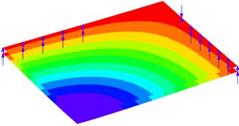
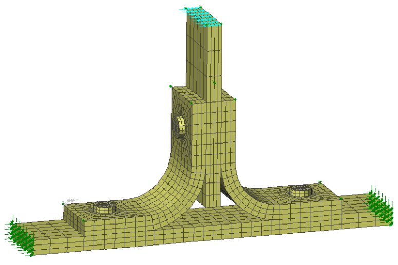
Modelling
3D models of both T-joint types
were created in LUSAS Composite and a direct tension, a
lateral and an inclined load case applied to each model. For the
direct tension loadcase, and because of symmetry, only a
half-model needed to be defined. Whilst modelling of individual
laminate plies is possible in LUSAS, NPL decided to simplify
models by carrying out global modelling of the GRP layers using an
orthotropic solid material model. with properties obtained from
its in-house CoDA software. A nonlinear material model was used
for the aluminum T-joint. To model the clamping force of the
torqued bolts a prestress force was applied to the shank of each
bolt prior to loading the model with the chosen applied loading.
Correct modelling of the contacting
surfaces of components is the key to analyses of this type so
extensive use was made of the LUSAS slideline facility. Slidelines
automatically take care of any frictional contact between
contacting components. In all, 42 sets of slidelines covered the
various contact situations that would occur in the analysis of the
full T-joint model as used in the lateral and inclined loading
analyses.
Slidelines were used to model:
-
Initial contact between web,
base and flange plates.
-
Initial contact between the
underside of the bolt heads to web, base and flange plates.
-
Loss of, or increased contact
between flanges and web/base plates.
-
Potential contact between the
bolt shanks and holes.
Joint
failure was to be regarded as yielding of the aluminium or, for
the GRP model, exceeding the failure strength of the composite
material. For this, predicted failure loads were obtained for
positions at the interface between the flange and the base and web
plates and for a point mid-way around the radii of the flange.
Laboratory tests involving strain
gauges were also carried out on T-joints as part of the
investigation and the results from these were used to verify the
accuracy of the LUSAS results.
Results
Analysis with LUSAS showed that for
the bolted aluminum joints under direct tension elongation of the
bolt holes would initially occur in the base plate, followed by
similar damage in the web holes. Ultimate failure occured midway
around the web due to high stress and strain concentrations in
this region. Mike Gower, Research Scientist at NPL said: "In
the direct tension case for the aluminium joint we wanted to
predict where yielding was occurring and to what extent in order
to fatigue test a sample joint using a percentage of the yielding
load. For the GRP T-joint, by looking at various stresses in the
model we could determine at which load increment the material
strength values were exceeded."
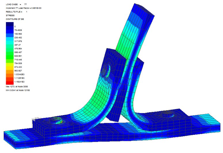
For
the GRP T-joint, Mike Gower said: "We got very good agreement
with LUSAS using the Hashin failure model. At first sight it
looked as if the GRP flanges were delaminating mid-way around the
web, but in fact LUSAS and physical measurements showed that the
peak stresses predicted by the Hashin failure index actually
occured under the bolt at the interface between the unidirectional
and woven plies, before then propagating around the curve of the
flange component"
For the direct tension load case
LUSAS overpredicted the results slightly. This was thought to be
due to modelling the base plate supports with infinite stiffness
and with hindsight perhaps springs should have been used instead.
The yield loads, however, agreed very well. Results obtained from
laterally loading the joint were in similarly good agreement,
indicating that the modelling of the restraints had less effect
for this loading condition than for the direct tension loadcase.
"It was very useful to use LUSAS for this research work. I
found it very intuitive."
Mike Gower, Research Scientist, National Physical
Laboratory
Other LUSAS Composite case
studies:
|