Case Study
Design of carbon fibre mast, turret and boom components for a new yacht rig
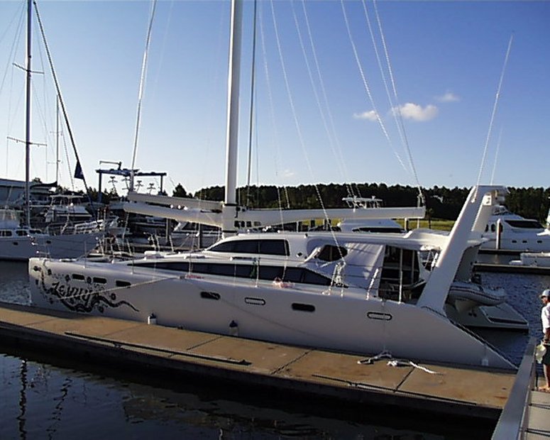
Carbonworks was
approached by one of its clients to design and supervise the construction of carbon
fibre yacht mast, turret and boom components for a fast-cruising 49 foot (15 metre)
catamaran being built on the Gold Coast in Australia. To help optimise the design of
the rig, linear buckling analysis, composite analysis, material testing and static stress
analysis was carried out using LUSAS Composite.
|
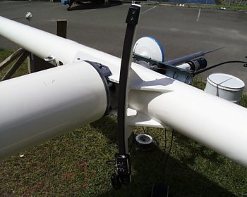
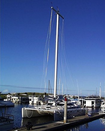
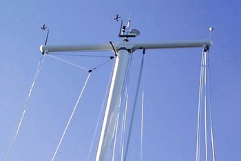
The rig differs from conventional rigs in that it is a
free-standing mast and "swing-rig" with an unusual headboard, which has been
called the "turret". The turret enables larger sails to be fitted to produce
more power. Being an unusual rig there was much debate on defining the design loadcases.
Carbonworks developed several draft loadcases and commissioned two other companies to do
the same. These loadcases were developed using non-linear rig models from specialist
sources. Over a period of two months this information was compiled and compared until a
final design loadcase was settled upon. The critical loads were determined to be ultimate
mast compression and forestay catenary tension. Ultimate load was developed at 40 knots
apparent and full sail of 120 square metres. Ultimate load is intended to be when the mast
breaks. This represents a mast compression in the order of 25 tonnes and a distributed
load down the 20m mast of 2N/mm. The turret transmits the full compression load from the
rigging to the mast, and is consequently very highly stressed.
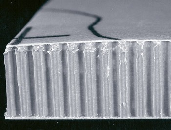
Parallel to this work, draft material specifications were developed from information
provided by the material suppliers and the preferred fabricators. The mast was made as a
pressure moulded component and the turret is to be made as a shrink-wrapped consolidated,
wound mandrel piece. Draft material specifications were used to produce preliminary mast
and turret models. The turret had a target weight of 60kg. The draft turret model showed
this was feasible, so the turret design was developed further resulting in a 57kg
component. The LUSAS Composite modeller proved to be very capable in allowing
changes in specifications and geometry to be implemented rapidly. Some designs were
imported from Autocad and Cadkey drafting packages using the IGES translation and import
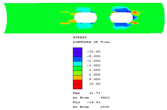
facility. Tsai-Wu and Tsai-Wu-Cowin theories were used to determine First Ply Failure
situations. Linear buckling analysis was used to ensure that mast and turret buckled at a
load factor of 1.2 or greater. |
|
| |
|
|
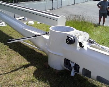
The turret is 6m long, approximately 230mm in
diameter, and made from prepreg carbon fibre. The turret was modelled in LUSAS Composite
using semiloof thin shell elements and consisted of laminates with 7 to 22 layers. The
turret has several holes for halyards and control lines in areas of maximum compression.
LUSAS Composite was used to determine if these holes contributed to premature
buckling, and to assess how much unidirectional carbon fibre was needed each side of the
holes to act as a bypass for the loadpath. In addition, the attachment points to the mast
are slender webs and LUSAS Composite helped determine their minimum thickness to
prevent buckling. The design cycle consisted of building a very thin model of about half
the target weight, based upon hand calculations. Linear buckling analysis was done to
determine where it would fail. The failed area was thickened, then run again, usually
moving the buckle to somewhere else. When the model was failing at about a load factor of
one, a stress analysis was done to check the stress regime. Some areas had to be
reinforced due to overloading, either by ply orientation changes or using more
sublaminates in patches. |
|
When the component designs were complete and agreed to by
the Client, Fabricator, and the Designer, material samples were made and tested to verify
the draft material specifications. A couple of surprises were found with low laminate
modulus and low tensile strengths. LUSAS Composite was also used to carry-out
simulated tensile and compressive tests in parallel with the physical tests. The laminate
failure criteria was then tuned to the physical tests, a safety factor added and the draft
models re-analysed and modified to accommodate the changed material specifications.
Changes were not too dramatic and again LUSAS Composite allowed easy modification
of the models. After a review of the models and checking up to date information, final
drawings and laminate schedules were released and the mast was built.
The project provided an opportunity to
complete a design using the linear buckling, composite analysis, material testing and
static stress analysis capabilities of LUSAS Composite.
"With the associative modelling capabilities of the LUSAS
Composite modeller, design changes were easily incorporated into the finite element models. This
resulted in rig components that were designed to the client's specification, had a high
reliability, and were optimised for the imposed loadings".
Peter Schwarzel,
Carbonworks
Other LUSAS Composite case
studies:
|
|
Software Information
|