Software Tour
Tank model and analysis
types supported
Easily create 2D and 3D tank models from common tank definition data. Carry out preliminary studies using any of the 2D tank modelling options that are available, before moving on developing and investigating the suitability of designs in more detail using 3D shell or 3D solid models
For preliminary analysis:
-
2D axisymmetric structural
-
2D axisymmetric staged construction
-
2D axisymmetric coupled thermal/structural
-
2D beam-stick seismic
For detailed analysis:
Use 3D shell
models for design checks. Use 3D solid models for a more
representatative spillage analysis. Undertake comparative studies by copying tank
definitions and re-creating models from revised data.
Examples of models created
by the wizards are shown below.
2D Axisymmetric
Structural
Model features are defined
in individual groups for easier updating of the model and processing
of results. For concrete tanks, only the outer tank is modelled, and is
investigated using 16 static loadcases.
2D Axisymmetric
Staged Construction
In addition to the groups
of features defined in the 2D axisymmetic structural model, extra groups are set-up to
simplify the activation and deactivation of features when modelling
the construction stages. Up to thirteen construction stages are
automatically created by the wizard, and the nonlinear analysis
sequence used ensures that the stresses and strains from a previous stage are inherited in the following stage.
2D Axisymmetric
Coupled Thermal/Structural
Used to obtain the
temperature variation through the thickness of the structure and to
obtain the thermal stress and strains induced by the temperature
gradient. Typically followed by a structural analysis that uses the
temperature distribution as its input loading - commonly known as a coupled
themal/structural analysis.
2D Beam-Stick
Seismic
A lumped mass beam-stick
model is used to perform a dynamic analysis under earthquake
conditions. The adopted arrangement of components captures the complex
seismic behaviour of the liquid tank system in a simplified but
accurate model. A response spectrum corresponding to ASCE is defined
by the wizard by default, but others and user-defined spectrums are
available.
Some
loadings specified or generated from some 2D analyses (such as applied
loading, live loadings, thermal or seismic effects) may be converted
into equivalent structural or temperature and used in a 3D model.
3D Shell Static
Structural
Used when tank loadings
are not axisymmetric, and used to create design results. All loading defined for the 2D axisymmetric
structural is also used for this model, and wind loading can also be applied.
Half and full models may be created.
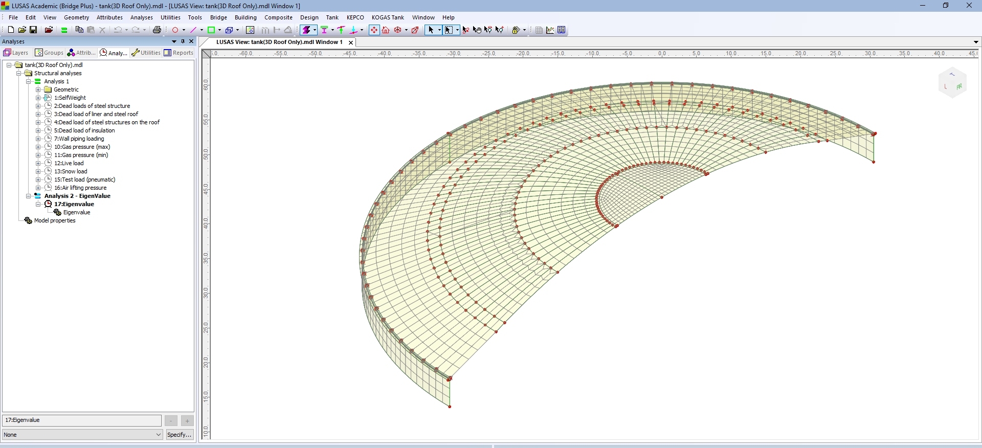
3D Shell roof-only
Used for generating half or full models of a steel tank roof
(if that is of sole interest) for a linear structural analysis with all loading as defined in the tank definition.
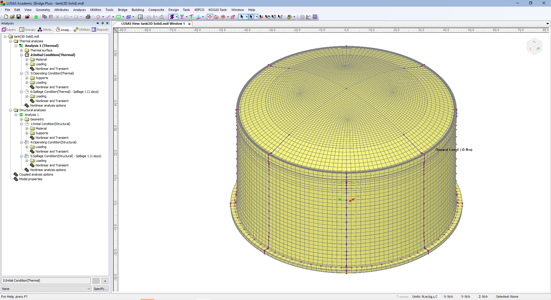
3D
Solid Coupled/Thermal Structural
Used to create a coupled thermal-structural, full, half or quarter sized 3D solid tank model, with explicitly modelled wall reinforcement, ringbeam reinforcement and spillage scenarios.
Models created
Models created by the
wizards are generated with all mesh, geometric properties, attributes,
supports and loadings assigned to the model, and with features grouped
according to type.
Analysis and
design capabilities
|
|
|
- Linear/nonlinear buckling
|
|
|
- Coupled thermal/structural
|
|
|
|
- Nonlinear concrete cracking
|
|
|
|
- Soil-structure interaction
|
|
General LUSAS facilities also enable modelling of blast analysis or a fire in an adjacent tank.
Results
Once solved:
- View results for all or selected
parts of a model using separate layers for diagram, contour,
vector and discrete value data.
- Select loadcases individually for
each view window, and display multiple views of the model, with
each window showing results for different loadcases.
- Manually specify basic load
combinations, defining loadcases to be included and load factors
to be used.
- Use Smart Combinations to generate
maximum and minimum results, reducing the number of combinations
and envelopes required.
- Define envelopes of multiple
loadcases to provide maximum and minimum results.
- Plot bending moment and shear force
diagrams and visualise structural deflections.
- Display results in global or local
directions, in element directions, or at any specified
orientation.
- Selectively output results to
spreadsheet applications for additional calculation and graphing
uses.
- For concrete modelling, plot crack
width contours, crack patterns and values for supported design
codes.
- Use inspection locations to obtain results
for user-defined positions of interest on a model.
- Transform and display results in
global or local directions, in element directions, or at any
specified orientation.
Transformed results plots
of component Nx and Ny are shown below.
Graphs showing, for
example, the variation of moment Mx with wall height can be generated
from selections made on the model.
Exporting of
forces to spreadsheets
In addition to on-screen
viewing of results, exporting facilities also exist to automatically convert stress
distributions at chosen slicing locations on models into section
forces and output to a spreadsheet. For example, for a 2D axisymmetric
model, slices taken through a wall section for component SY can be
used to compute vertical axial forces and bending moment.
For a 3D shell model,
similar section forces based upon angular values are extracted by that
wizard and exported to a spreadsheet
Continue the
tour...
Find out more
|