Software Option for Bridge and
Civil & Structural products
RC Frame Design
The LUSAS RC Frame Design
option builds upon the renowned modelling and analysis
capabilities of LUSAS and extends the engineer�s workflow to
allow design code checking of reinforced concrete members.
It
provides
design code checking of regular and arbitrary shaped reinforced
concrete decks/beams, piers/columns and piles subject to bending and
axial force. Tapering and voided members are supported. Design checks due to bending
with or without axial force can be carried out for reinforced
concrete sections at the Ultimate Limit State (ULS) and
Serviceability limit states (SLS).
The following design codes are
currently supported:
AASHTO LRFD 8th and 9th LRFD
Edition, ACI-318-19 (USA)
AS5100.5-2017 (Australia)
CSA S6-14 and CSA S6:19
(Canada)
EN1992-1:2004
and EN1992-2:2005
(Europe)
IRC:112-2011 (India)
Defining reinforcement
Define layers of reinforcement by
entering rows of table data (cover, allowance for links, number of bars, bar diameter etc.)
for each numbered face in a chosen cross-section.
Bars are spaced equally, and where
bars in different faces are shown to clash, end bars from selected
faces may be omitted.
Use multiple rows of table data to
position bars in multiple layers within a face, or to specify more
dense or sparse reinforcement within a layer. Alternating bar
arrangements and manual bar placements are also supported.
Bar spacing, as used for
determination of crack widths, is calculated by considering where
each bar, or any bundled bars are with respect to other bars in
the section.
Specify how individual reinforcement
arrangements apply over a length of a line, or over multiple lines
that represent a concrete member.
Typical
section
reinforcement definitions.
Specifying
multiple reinforcement arrangements for a member (or
series of members)
Viewing design results
Select results components
for individual design checks, and obtain maximum
utilisation factors in all, or selected members.
View results as Utilisation
ratios on a results viewing layer for a selected design
code, and active loadcase, load combination or envelope.
Produce a tabular summary of
design check results for selected members and loadcases,
view detailed results and generate interaction diagrams.
Save results for use with
Microsoft Excel, or add them to a model report, and each
time the report is generated the reported design data will
be automatically updated to match the current state of the
model.
Extend your workflow
from analysis into RC deck/beam, pier/column and pile design.
View results as
Utilisation ratios on a results viewing layer for a selected
design code, and active loadcase, load combination or envelope.
Produce summary
information in tabular and report-based formats and easily see
pass/fail values
Create design reports
individually or append them to the report for the whole model. Mix
summary reports for the whole structure with detailed reports of
critical members. Create templates to speed reproduction of
similar content.
Learn it fast.
Existing users can easily apply the new RC frame designer because
it works in a similar way to other tools they have become familiar
with.
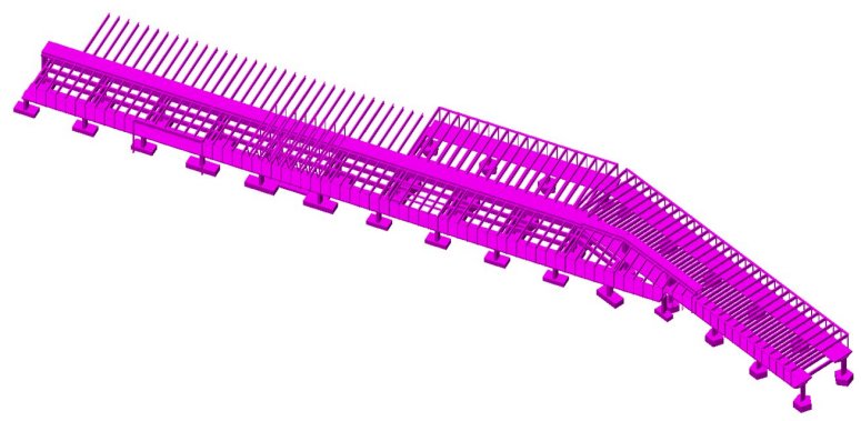
The capacity of the RC frame design module to deal with complex section geometry has been fundamental in allowing us to carry out
design checking of the individual members of the structure within a limited timescale.
Its use is straightforward, from the definition of
the geometric properties, to the post-processing and viewing of the results.
Ultimate and serviceability limit state checks can be viewed
by either plotting contour maps of the utilization coefficient on members of the structure, or by tabulating all or selected details for
members of interest and including that data in a model calculation
report.
LUSAS is a trademark and
trading name of Finite Element Analysis Ltd. Copyright 1982 - 2025. Last
modified: January 06, 2025
. Privacy
policy.
Any modelling, design and analysis capabilities described are
dependent upon the LUSAS software product, version and option in use.