Software Option for LUSAS Bridge
versions
Steel and Composite Deck Designer (PontiEC4)
The Steel and Composite Deck Designer
software option carries out comprehensive
calculations for multiple sections on steel or steel/composite bridge decks to
the Eurocodes, allowing otherwise
time-consuming and error-prone manual design calculations to be carried out
efficiently.
- Perform rapid design calculations covering ULS
bending, stress, shear and interaction; SLS stress, web breathing and
fatigue checks for main members and connectors.
- Consider multiple sections with different properties (haunches,
stiffeners, etc), and also bolted connections.
- Output results in tabbed dialogs
that visually show values that pass or
fail.
- Easily create graphs and a report containing all input data and output with
references to the Eurocode clauses.
Force
and moment results for selected bridge deck elements are provided by
LUSAS and loadcase combinations defined within LUSAS are associated
with design limit states and phases defined in the Steel and Composite
Deck Designer.
For steel and composite deck design to
AASHTO 8th Edition see Software Option - Composite Bridge Deck Design.
Design members
Use the
Steel Composite Bridge Wizard
to automatically create the required Composite Bridge Deck Design members
when bridge design materials are additionally specified for all I-girders.
Add details for transverse stiffener design also.
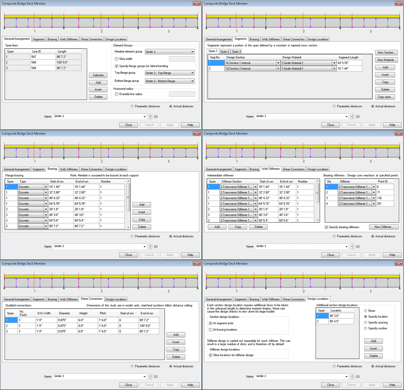
Define additional design
details for each design member using a tabbed dialog. Span lengths,
segments (a portion of a span defined by a constant or tapered
section), bracing locations, web stiffeners, shear connectors and
locations at which design checks will be made, can all be specified.
|
|
|
Composite Bridge Deck Design
member dialog |
Design checks supported
|
Carry out design checks
for any number of construction phases:
- Phase 1
– Self weight
- Phase 2a
– Permanent loads
- Phase 2b
– Concrete Shrinkage
- Phase 2c
– Imposed deformations/prestressing
- Phase 3a
– Thermal actions
- Phase 3
b – Traffic loads
|
|
For each construction
phase, design checks are made for each of the following combinations:
- ULS
Fundamental – EN 1990 6.4.3.2 (3)
- SLS
Characteristic – EN 1990 6.5.3 (2a)
- SLS
Frequent – EN 1990 6.5.3 (2b)
- Fatigue
– EN 1992-1-1 6.8.3
|
Typical application
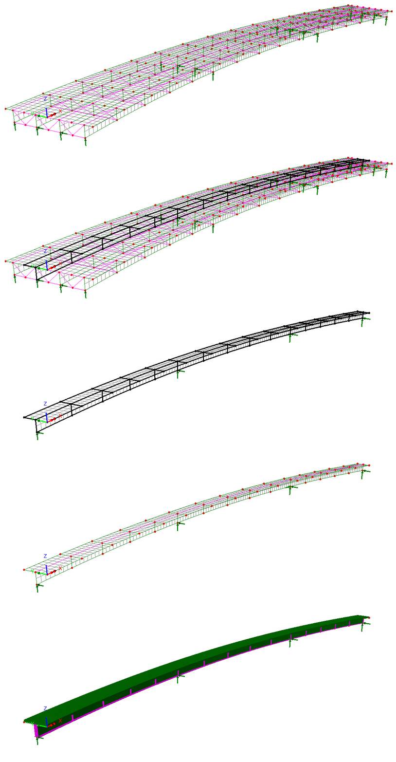
LUSAS model
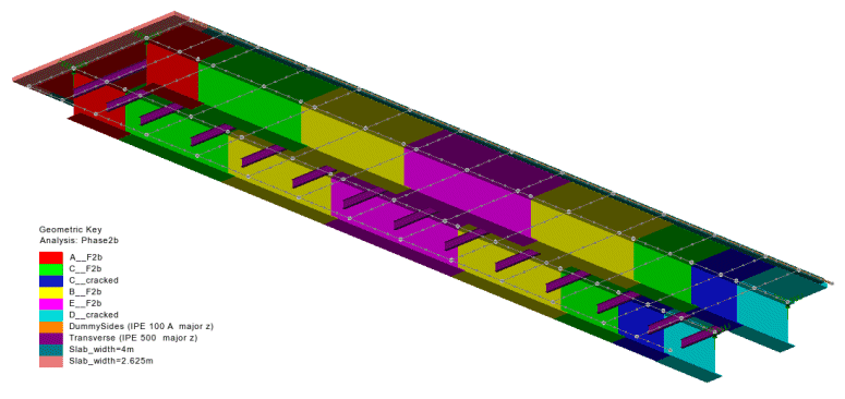
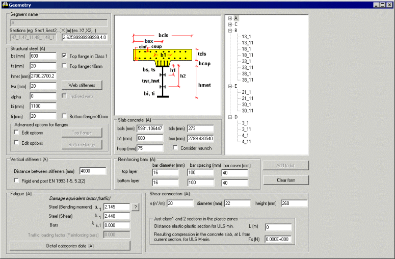
Section definition
 |
| Deck
section information is defined in the Geometry dialog of the Deck Designer and is organized in
a tree structure. |
Advanced options
|
|
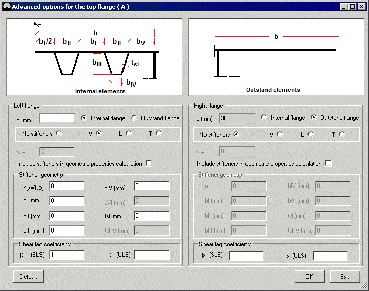
| Advanced options
allow the specification of web and flange stiffeners and
permit the buckling of longitudinally stiffened flanges to be considered. |
Bolted connections
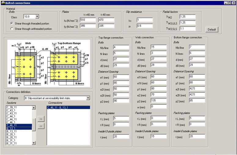 |
| Bolted
connection details are supported |
Material definition
|
|
|
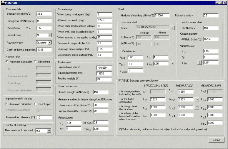
Input of material properties is straightforward and
can be adjusted to suit project requirements. |
Assistance with setting codified
parameters
|
Dialogs assist with the
calculation of effective widths and shear lag, and the setting
codified parameters such as fatigue damage equivalent factors
for shear studs, structural steel and reinforcing bars
|
Forces and Moments
|
|
|
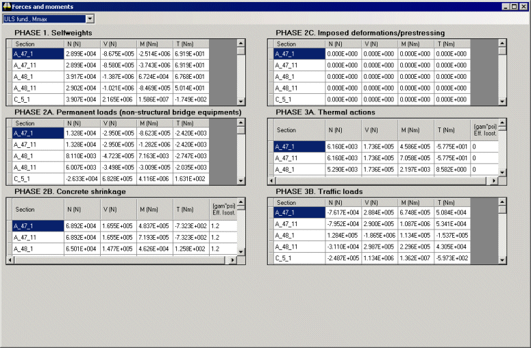
Construction stages and in-service
conditions are assimilated and design combinations organised
in groups.
Load effects for
the various sections to be checked are displayed in a
spreadsheet style. |
Design calculations and results output
Automated ULS, SLS, fatigue and
other calculations
Results
- Section properties
- Primary (isostatic) effects of shrinkage and temperature change
- Creep and shrinkage coefficients (EN
1992-1-1, App B)
- Classification of sections (EN
1993-1-1, Table 5.2)
- Ultimate bending check for Class 1 & 2 sections
(EN 1993-1-1, 6.2.5)
- Stress checks for Class 3 and Class 4 sections
(EN 1993-1-5, Section 4)
- Ultimate shear and web buckling (EN
1993-1-5, Section 5)
- Bending-shear interaction (EN
1993-1-5, Section 7)
- SLS stress checks (EN 1994-2, 7.2.2 (5)
and EN1993-2, 7.3)
- SLS web breathing check (EN1993-2,
7.4)
- Reinforced concrete crack checks (EN
1994-2, 7.4(3))
- ULS, SLS and fatigue checks for connectors
(EN 1994-2, 6.6
and 6.8)
- ULS, SLS bolted connections (EN 1993-1-8)
- Fatigue checks for both structural steel and reinforcement components (EN 1993-1-9, EN 1994-2, EN 1993-2)
- Transverse and longitudinal
stiffener checks (EN 1993-1-5, 9.2.1 and 9.3.3)
|
|
|
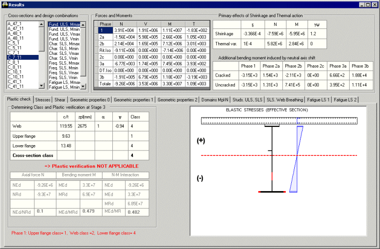
A multi-tabbed results
dialog gives access to the results for each of the design checks made
for each deck section. |
Results pages
|
|
|
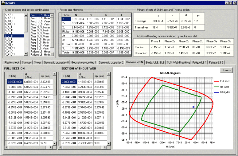
Emphasis on descriptive
graphics e.g. bending-shear interaction diagram with the web
contribution included or excluded |
Results Summary
|
|
|
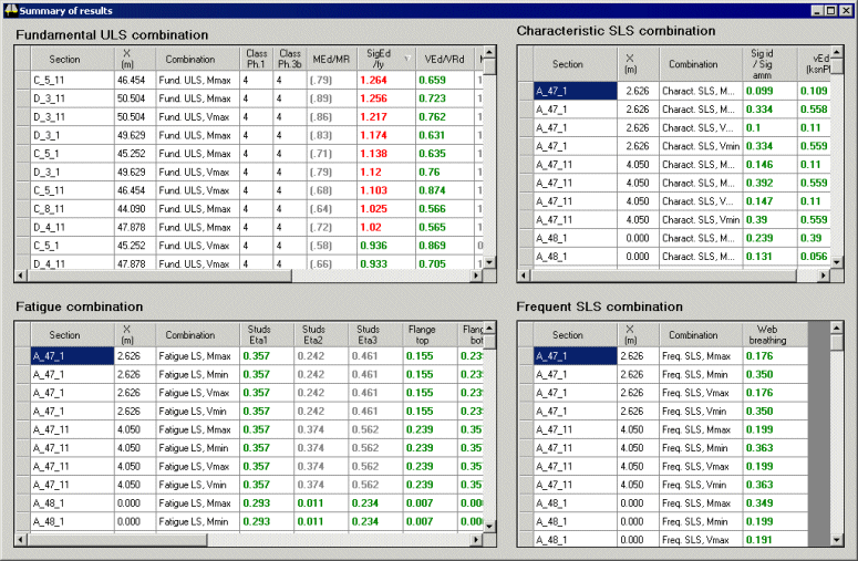
A Results summary dialog
shows (as on all dialogs) at-a-glance viewing of pass / fail values for sections.
Values passing a design check are shown in green, those failing are
shown in red) |
Crack checking
|
|
|
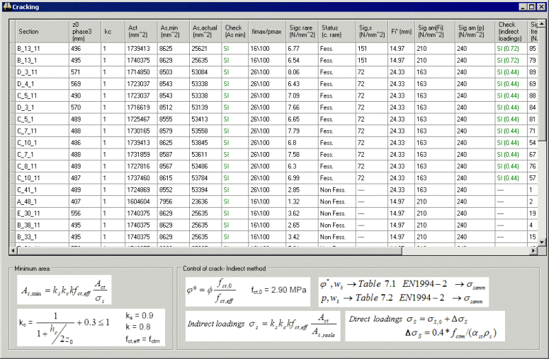
Where required,
reinforced concrete crack width limitation can be carried out
using the indirect method according to EN 1994-2 7.4 (3). |
Graphing
|
|
|
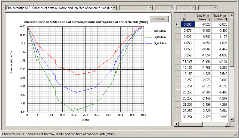
Pre-defined
graphs of utilisation factors, stresses, longitudinal shear
per unit length, force and moments, etc. are easily
plotted.
User-defined graphs can also be created. |
Reports
|
|
|
|
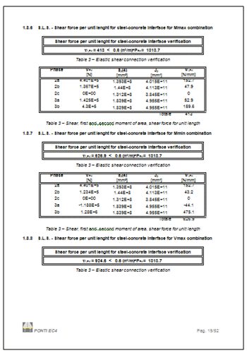
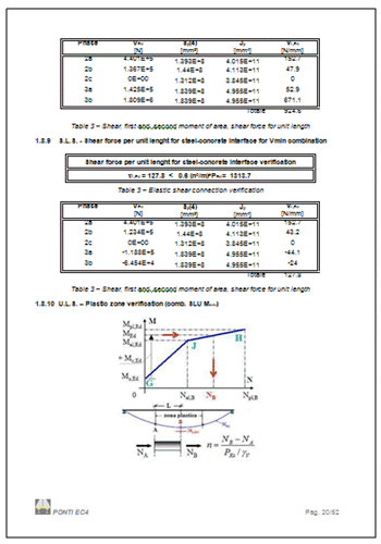
Reports,
containing all or selected input and results data, are created
with references to Eurocode clauses. |
Section Optimisation
Section optimisation can be carried out by
editing the geometry/material data in the Deck Designer and then
viewing (also in the Designer) how the changes have affected
the results. If required, the revised properties can be re-exported to
LUSAS to carry out a final iteration and check, but this will not always be
necessary.
Bridge types supported
|
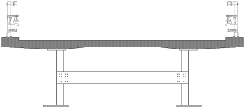
Composite
I-girder |
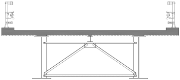
Composite
I-girder |
|
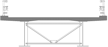
Composite
I-girder |
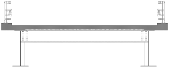
Composite ladder
deck |
|
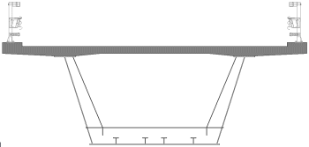
Composite box
girder |

Composite box girders |
|
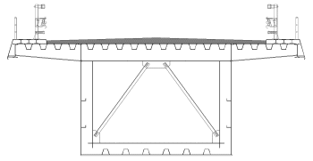
Steel box girder
with orthotropic plate |
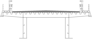
Steel girder with orthotropic plate |
|

Half-through bridge |

Half-through bridge |
Some projects undertaken using
the Steel and Composite Deck Designer
|
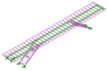
|
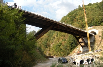
|
|
Bridge over the
Serchio river, near Castelnuovo di Garfagnana, Tuscany, Italy |
For Composite Deck Design
to AASHTO 8th Edition (2017) use the Composite
Bridge Deck Design option.
|
|
Software Information
|