Case Study
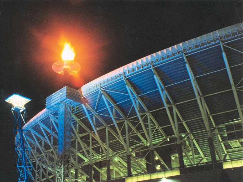
The Olympic
Cauldron
- Stainless steel gas burning structure
- 3D static, dynamic and buckling analysis
- Calculation of structural displacements for critical service
connections
Tierney & Partners, one of
the leading Australian Civil & Structural Engineering Consultancies
was responsible
for the structural design of the Olympic Cauldron, mast and transport components
used at
the opening ceremony of the Sydney 2000 Olympic Games. LUSAS Civil & Structural
analysis was used to assist with the development of this prestigious project.
Overview
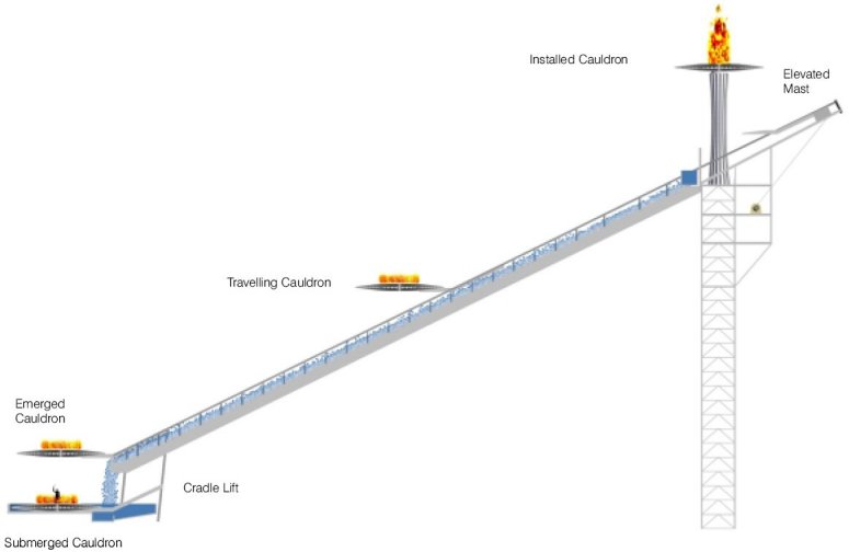
The 8.5 tonne cauldron was designed
to be a perforated, corrugated shell structure fabricated from
stainless steel. It has an overall diameter of 10m and tapers from
0.85m thick at centre down to 0.15m thick at the edge. During the
opening ceremony it was raised from its submerged resting place
beneath ground level and traveled up an inclined cradle lift to a
point from where it is then lifted up to a final position on a mast
50m above the ground.
The complex structure required an
accurate stiffness assessment to be made. This was critical as the
mechanical components needed to compensate for deflections at
various stages of transport.
Design development
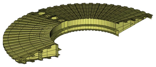
The cauldron was modelled in LUSAS
Civil & Structural using 3D shell elements and 3D static,
dynamic and buckling analysis was carried out to investigate self
weight, wind, and dynamic effects caused during the transporting the
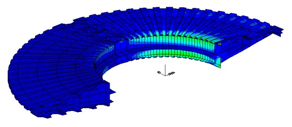
cauldron to its final resting place. LUSAS showed how the cauldron
structure would perform under various transient loading and
supporting conditions, and highlighted a number of elements with
relatively high local stresses. If some elements or connections were
to fail during use it was possible to foresee the re-arrangement of
the load path and overall behaviour. This further increased
confidence in the LUSAS model and hence the structure as a whole.
The LUSAS results confirmed
preliminary assumptions that the stiffness of the shell, although
corrugated, plays a major role in the strength and stiffness of the
cauldron structure. Relying on the contribution of the corrugated
and perforated shell, discretely connected to the internal frame,
enabled this frame to be extremely light. Apart from an obvious cost
effect, this proved to be critical as the project was nearing its
completion and the weight of equipment was gradually increased from
an initial 5 tonnes to a final 8.5 tonnes.
| Results obtained were in the expected
range. In fact, first results showed deflections slightly below
initial estimates. However, this "benefit" was soon lost
as more and more gas, electrical and mechanical equipment was added,
increasing the original weight of cauldron by over 60% at the end of
project. Due to presence of the shell the cauldron structure was
able to absorb this increase in load without adversely affecting its
performance. Furthermore, some connections, and in particular those
critical ones near the cradle support for the cantilevering
condition, had to be significantly modified to accommodate
operational requirements (attaching and detaching gas lines and
engaging/disengaging mechanical parts). Time did not allow
re-modelling of the cauldron to test it against proposed changes.
However, as a thorough understanding of the behaviour of the
cauldron components had already been gained, it sufficed to alter
some properties of the relevant components of the model, which
enabled quick and practical modifications to be approved within
hours of the request for change.
|
|
As Zlatko Gashi, engineer on the project says: 'when reliable and
accurate understanding of the behaviour of the structure is required, it can only be
achieved by taking into account all relevant structural components. Neglecting some
components could grossly underestimate the strength and stiffness of the structure.
Complex, sophisticated structures require a modelling and analysis tool such as LUSAS
which can handle all the aspects of structural design, without burdening the designer with
a further complexity of tool itself. In addition, careful planning before the
modelling, and envisaging potential future modifications and critical issues, is a key to
successful design, and ensures that all benefits can be obtained from the model throughout
the design and construction stage of the project."
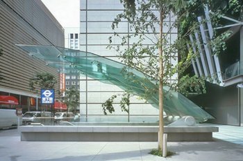
Legacy
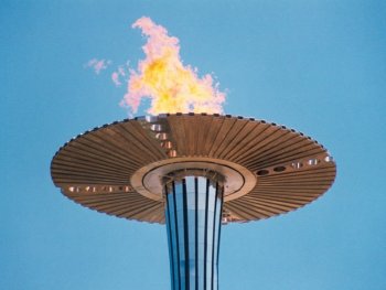
After the Games, The Cauldron was
relocated to Cathy Freeman Park (formerly The Overflow), a few
hundred metres from the Olympic Stadium, where it now stands on 24
stainless steel columns and showers water down on those passing
beneath it. At its base the names of the 1,972 Olympic Medalists and
2,627 Paralympic Medallists at the Sydney Games are recorded on
gold, silver and bronze nameplates.
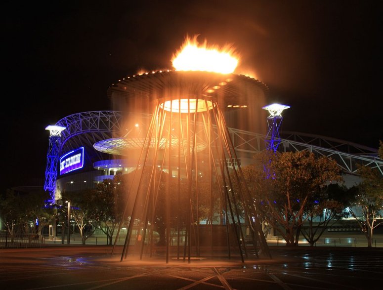
The Cauldron in its
legacy form as a sculpture/fountain in Cathy Freeman Park.
"Complex, sophisticated structures require a modelling and analysis tool such as LUSAS
which can handle all the aspects of structural design, without burdening the designer with
a further complexity of tool itself."
Zlatko Gashi,
Project Engineer, Tierney and Partners
Find out more
Other LUSAS Civil &
Structural case studies:
|
|
Software Information
|