Case Study
Staged Construction Analysis of
a Concrete Shaft on the Dublin Port Tunnel Project
- Staged construction analysis of large diameter concrete shaft
- Investigation into hole cutting sequence
- Assessment of wall strengthening options
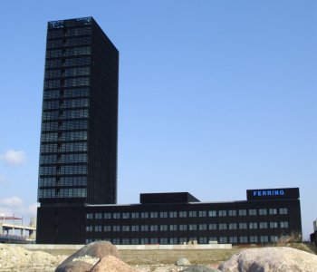
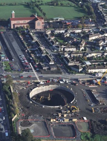
The Dublin Port Tunnel in Ireland runs
from the M1 motorway at Santry to Dublin Port at East Wall. Its primary purpose is to
provide good access to Dublin Port, as well as relieving traffic congestion in the city. A
2.4km length of the route requires twin bored tunnels to be cut in stiff Boulder Clay and
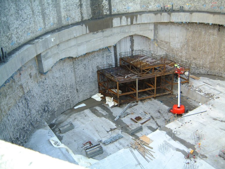
Limestone. To provide access for the tunnel boring machines (TBM) for this section of the
route a 60m diameter, 32m deep shaft with 1.5m thick in-situ concrete diaphragm walls
needed to be constructed. Once the TBM's are in place they each cut 13m diameter openings
through the shaft wall and bore a length of tunnel before turning around and re-entering
the shaft from the other direction. To assess the manner in which the stress
re-distribution takes place around the openings and to investigate the potential internal
strengthening options Haswell Consulting Engineers
used LUSAS Civil & Structural analysis software.
| A LUSAS model of the
complete shaft was created and geotechnical loadings, provided by a third party, were
applied. The shaft was analysed initally in isolation prior to the construction of any
tunnel openings. Crane loads were then added and staged construction analyses were carried
out by introducing the tunnel openings in a pre-defined order and taking into account all
applied loads and the manner and stage of construction at which they are applied. For each
opening cut by the boring machines plots of deformation, shear stress, bending moment and
hoop stress were produced. By deactivating the elements defining each hole in turn the
sequence of creating the holes could be modelled and the results from the previous
analysis were retained by LUSAS as the starting point for the subsequent one. |
|
|
|
| Graphs
of results sliced through the holes were particularly useful. One interesting observation
was LUSAS showed that an analysis using only a quarter model would not take account of the
accumulative influence of the other tunnel openings. In parallel, the Contractor used
another software package to analyse one quarter of the shaft with one opening. Comparison
between the two sets of results showed an acceptable level of agreement, taking into
account the different assumptions made in each model. However, the results of the
Contractors analysis were implemented in the design which was enhanced by the results
produced by LUSAS. After all four holes had been cut the eventual stresses around each
differed. Dr Ala Sainak, formerly of Haswell Consulting Engineers but now Senior
Geotechnical Engineer at Halcrow explains: "It
was thought that the stress distribution around one cut hole would be the same as for an
adjacent hole but the analysis with LUSAS proved otherwise and showed that it was more
appropriate to analyse it as a full model rather than a quarter model.
|
|
|
|
|
Shear stress values and bending moments in the wall
caused by cutting holes through the shaft were of an acceptable value but a greater factor
of safety was required. To try and achieve this three wall stiffening options were
considered. These all involved casting additional concrete in place prior to any cutting
out of holes.
- Option 1 : The provision of an inner 2m thickening to the lower section
of the 1.5m wall. LUSAS analyses showed that this didn't help transmit any significant
loading because the outer wall had already been built and hence it retained its initial
stresses.
- Option 2 : The provision of two, 2m x 2m ring beams, one above the crown
of the tunnel openings and at the base of the wall. LUSAS showed that the additional ring
beam accommodated most of the hoop loads but failed in attracting the locally
redistributed stresses, bending moments and shear forces
- Option 3 : Provide two ring beams and a reinforced section of a similar
thickness to the ring beams to the region surrounding the hole. LUSAS showed that this
option also failed to attract and reduce the locked-in stresses.
With the aid of LUSAS all of these potential options were rejected for
being either too expensive to implement or for failing to achieve the desired result. The
eventual solution was to construct one ring beam above the crown of the tunnel openings
and in addition use very high yield and large diameter steel reinforcement in the concrete
segments either side of the holes as well as in the concrete segments containing the holes
to overcome the large shears produced by the cutting of the tunnel holes.
|
|
Find out more
Other LUSAS Civil &
Structural case studies:
|
|
Software Information
|