Case Study
Share this
article
Design
and analysis
of above-ground full containment LNG storage tanks
-
Development of the world's
largest above ground LNG tank
-
Static, dynamic, thermal and
nonlinear analysis
-
Strict design requirements
met
KOGAS Gas Technology Corporation (KOGAS-Tech)
is using LUSAS Civil & Structural software to help
develop and continually improve its range of above ground full
containment Liquified Natural Gas tanks. With the assistance of
LUSAS engineering consultancy services LNG storage tank sizes of
140,000m3 were initially developed but now, using LUSAS
Civil & Structural, an above ground full containment
LNG tank with a capacity of 200,000m3 has been analysed
and optimised. When completed it became the
largest above ground full containment LNG storage tank in the
world.
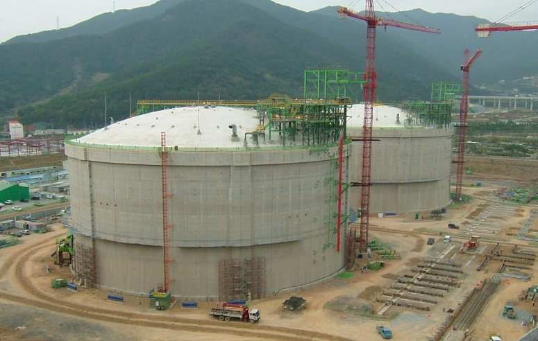
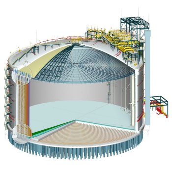
Tank development
Over
the years KOGAS-Tech has developed two distinct types of
above-ground post-tensioned concrete containment tanks. One
involves the use of a proprietary inner membrane system, and the
other comprises a steel nickel inner tank lining. Both are of a
140,000m3 capacity and have been installed at the
Pyeongtaek and Tongyeong facilities in South Korea. With the use of LUSAS software
KOGAS-Tech has now developed a 200,000m3 above ground
tank for the Pyeongtaek facility. Similar in nature to its smaller
brother it has a 37.6m high nickel steel inner tank of 84m
diameter insulated from a 86.4m inside diameter post-tensioned
concrete wall. The steel tank sits on a concrete base slab
supported by small diameter piles at close centres. The overall
tank height to the top of the roof slab is 52.8m.
|
Analyses undertaken
In analysing
and developing its range of tanks KOGAS-Tech performs
numerous finite element analyses with LUSAS including:
-
Static analysis
-
Wind loading
-
Modal and seismic analysis
-
Temperature modelling
-
Leakage modelling
-
Prestress / post-tensioning
-
Burn-out modelling
-
Relief valve heat flux modelling
-
Soil-structure interaction
|
|
Static
analysis
For static analysis, 2D axisymmetric solid element
and 3D shell element models are built and numerous static linear
analysis loadcases are defined for various parts of the structure
with the roof, the walls, the base slab etc being loaded
independently. Load combinations then allow the effects of the
multiple loadcases to be assessed.
Modal analysis
3D shell
element modelling and eigenvalue analysis of the LNG tank outer
shells and pressure relief platforms involves an examination of
both the uncoupled and coupled response of the two structures.
Lumped mass modelling is used for fluid/structure interaction of
the LNG and for soil/structure interaction of the pile
arrangements.
|
Wind load modelling
3D shell element
modelling is used to carry out wind load analysis of the LNG tank
outer shell. For this analysis, half-models can often be used due
symmetry of both tank geometry and loading. The wind load is
varied around the circumference of the outer walls using a Fourier
distribution providing a normal pressure on the forward face of
the structure and a suction to the rear face.
|
Seismic
analysis
Interactive
Modal Dynamics techniques are used in the calculation of the
dynamic seismic response. Operational Basis Earthquake (OBE) and
Safe Shutdown Earthquake analysis assessments are also run to
satisfy code requirements. The generated data from the structural
analysis is integrated to obtain base shear forces and bending
moments in the wall.
|
|
|
|
Thermal modelling
For thermal modelling, 2D
axisymmetric solid field and continuum elements are used and a
semi-coupled steady state thermal analyses of LNG tank outer walls
with insulation is performed. For this, an initial stress-free
temperature is applied to all elements, and combinations of
environmental conditions are considered for both the air and base
temperatures. Results plots of hoop stresses in the top and bottom
corners caused by a steady state thermal load are produced.
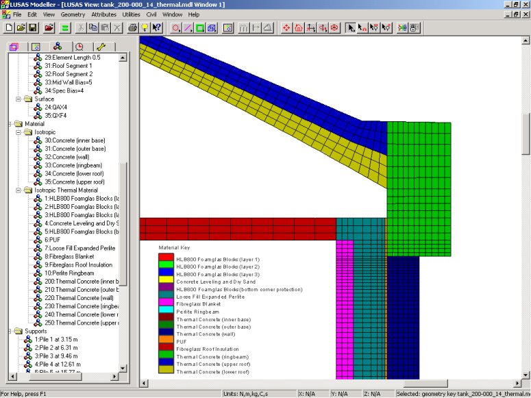 |
| Top corner
modelling |
| |
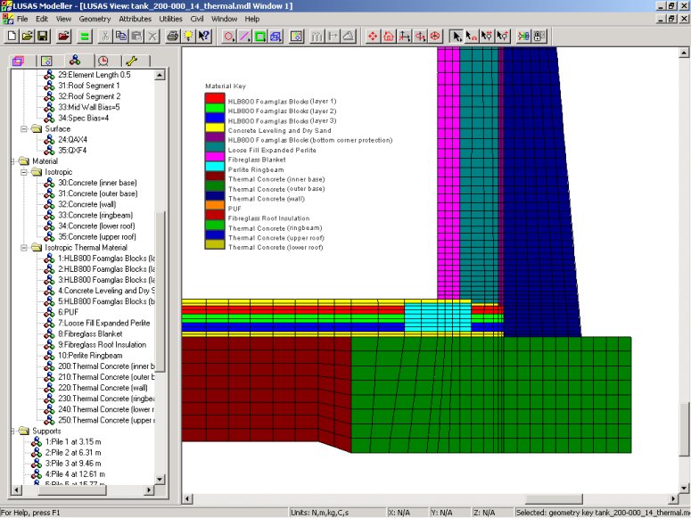 |
| Bottom corner
modelling |
Results plots of hoop stresses in the top and bottom
corners caused by a steady state thermal load are produced.
|
Leakage modelling
Leakage
modelling analysis investigates the effect of LNG spillage from
the inner steel tank onto the Polyurethane Foam (PUF) insulation
on the inside of the outer concrete tank at five different
heights. The tank insulation is assumed to have been completely
destroyed up to each level of the LNG under consideration. 2D
axisymmetric solid field and continuum elements are used to model
the tank outer walls and insulation down to the top of each
leakage level. A semi-coupled steady state thermal analysis is
carried out to assess the effects of the leakage.
|
  |
|
Modelling
prestress tensioning
Large temporary
openings in the wall mean that it is necessary to limit the
effects of stress concentration caused by prestress forces.
Loadings for each set of cables, both horizontally and vertically,
are defined and assigned in separate load cases. These loadings
can then be combined in different ways to achieve the required
prestress sequence and/or loading pattern. Section slicing of the
model is used to obtain axial forces and bending moments in the
walls around the opening for selected load combinations.
|

|
Burn-out modelling
Modelling of a
burn-out scenario involves 2D axisymmetric solid field elements
and transient thermal analyses of the LNG tank outer walls. The
tank roof and insulation layers (except any PUF
layer), are assumed to have been destroyed, and are not included
in the analysis. Steady state conditions are initially applied for
a specified time. To model the burn-out situation, a temperature
load of a specified peak temperature reducing to -170�C over a
distance of 1.5m is moved down the inside of the tank at a
constant speed for the burn-out time under consideration.
|
Relief valve heat flux modelling
With
relief valve heat flux modelling, the tank bases are normally
excluded from an analysis because they are considered to be remote
from the heat flux loading. 3D solid field and continuum elements
are used for a semi-coupled transient thermal analyses of a
segment of an LNG tank.
An initial stress-free temperature is applied to all elements and
steady state conditions are established for an internal
temperature of �170�C and a specified mean annual external
temperature. A heat flux is then be applied to a specified region
on the top of the roof for the number of time steps under
consideration.
|
  |
"Using LUSAS
allows us to continuously improve our analysis, research and
development capability especially in nonlinear analysis. With
LUSAS we can ensure that our range of LNG tank designs always meets
the strict design requirements of our clients."
Hag-Goo Sung, Civil
& Arch Dept Manager, KOGAS-Tech
Share this
article
Find out more
Other LUSAS Civil &
Structural case studies:
|