 Case
Study Case
Study
Share this
article
Design of the Copenhagen
Opera House roof
-
Design of one of
the largest canopy roof structures in the world
-
Static, dynamic
and thermal assessment of the roof for in-service loadings
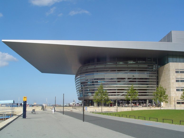
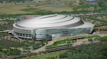
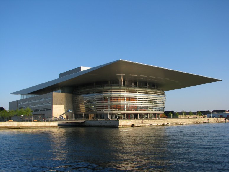
The roof of the new Copenhagen
Opera House is one of the largest canopy roof structures in the world,
and with plan dimensions of 158m by 90 m, it equates to the
size of three football fields. Ramboll used LUSAS finite element
analysis to assist with its innovative design of the structure in
order to ensure the necessary strength,
stability and dynamic response was achieved.
Overview
The roof is actually
comprised of two separate structures, the west roof and the east roof. The
78m x 98m west roof (shown right) is supported on ten columns which are located around the curved foyer, and on four
roller bearing supports located
on the interior concrete walls along the fly tower. The roof cantilevers
32m from the most westerly foyer columns and 21m in both the north and
south directions resulting in a maximum cantilever distance of 43m
when measured from the outer corner of the roof to the nearest foyer
column.
Because of its size and the
architect's requirement for
the roof to have the smallest possible depth and to taper to
virtually nothing the technical challenges for its design were many.
The eventual solution of
constructing the cantilever roof as a closed steel box is taken directly from
modern
steel bridge design.
|
Plan of the
cantilevered West roof showing area of box construction
(light grey)
and roof over foyer area (dark grey) |
Roof design and
construction
To design the roof a
number of technical challenges had to be overcome:
-
It had to be shown
that the structure possessed the necessary strength and stiffness
as preliminary
calculations had shown that it was almost impossible to design the
entire structure using common truss girders in two directions
-
It was important that in any final
roof design the first mode shapes involved not only localised
deformations of the outer corners but included deformations of the
whole roof structure to ensure a dynamic response of the roof within
acceptable limits.
-
It had to be able to
safely resist the large temperature differences in winter between the
cantilevered part and the internal roof over the foyer.
Ramboll chose to construct
the cantilever roof as a closed steel box because a significantly
higher flexural as well as torsional rigidity is obtained compared to
that for a traditional lattice roof structure. Bulkheads inside the
steel box are arranged at 5m spacing in both horizontal directions.
Longitudinal troughs are welded to the top and bottom plates only, as
is common in steel orthotropic bridge deck design. The plate thickness
is very thin in relation to typical bridge design, being limited to 6mm in the main part of the cantilevered structure and only increased
to 15mm in the region near the foyer columns. The roof structure could
not be designed as a closed box over the total area because of
differential temperatures, but was divided into a section made as a
box and the remaining section made of a number of girders.
The outer ring beam forms the inner closure of the box, and the
radial beams are designed so that the flaring of the beams can
absorb the horizontal axial stresses from the box structure. The foyer
balconies are supported by vertical hangers, which are anchored in
transverse beams spanning between the radial beams. Four roller bearings are arranged between the box structure and
the truss girders over the foyer area. The roller bearings allow
differential horizontal movements between the box structure and the
truss girders Along the three edges of the roof, outside the box
structure, truss girders are arranged to support the outer roof.
A slenderness ratio b/t of approximately 70 determined the distance between the troughs. To analyze stability problems in the slender plates,
Ramboll developed comprehensive new formulas for biaxial stress combinations, which included post-critical stresses and not only initial buckling stresses. These formulas
led to significantly lower plate thicknesses in the cantilevered roof.
|

|
|
West roof
structure showing main truss girders, inner and outer ring
beams, radial beams, extent of box girder construction
and perimeter cantilevered beams |
Static Analysis
The roof was designed for wind, snow and dead loads, as well as
for stresses caused by temperature and
for any settlement of the foyer columns.The wind load was based on results from wind tunnel tests.
A 3D LUSAS model of the closed box and the girders of the roof structure was used for
both static and dynamic analyses and these calculations determined all the normal stresses in the plates, parallel and perpendicular to the troughs, as well as the shear
stresses and all internal forces in each beam in the girders. The
static analysis proved the box structure to be an optimal solution, due to the use of stresses in both directions of the plates in combination with the shear stresses from the large torsional
moments in the structure.
Dynamic Behaviour
Preliminary studies for a
truss girder roof indicated an unacceptable repsonse. By constructing
the roof as a closed box the dynamic wind load was reduced to an
acceptable level, and damping devices were not required. Eigenvalue
analyses with LUSAS showed that the first mode shape for the closed
box roof involved not only local deflections of the outer corners, but
also a global deflection of the entire front of the roof. A wind
tunnel test was carried out to determine the time averaged wind load
on the structures and the fluctuating wind load, which were combined
with mode shapes, natural frequencies and modal masses of the
structures to determine the dynamic response. Differential Temperatures
|
The external cantilevered part of the roof forms a horseshoe
around the foyer area, and contracts in winter compressing the
structure over the foyer. Roller bearings sit between the
cantilevered box and the foyer girder portion of the roof and
release the differential horizontal deformations in the
north-south direction, and can transfer compression/tension
forces in the vertical direction. Carrying out a differential
temperature analysis with LUSAS showed how the structure over
the foyer contracts in the north-south direction, the girders
will deflect horizontally and the entire foyer structure moves
towards the east.
Hans Exner, Senior Chief
Engineer at Ramboll said: "All of us at Ramboll are
really proud of this building. It was a very valuable project
for our client, for Copenhagen and for ourselves. We used
LUSAS finite element analysis as the main structural analysis
tool for the design of the cantilevered roof and it assisted
us greatly in the solving of the main design challenges
involved."
The Opera House opened on 15 January,
2005. It received the 2008 International Association for Bridge &
Structural Engineering's Outstanding Structure Award, principally in
recognition of the innovative design of its roof. |
|
|
LUSAS modelling
of roof displacements caused by differential temperatures |
For
additional information see:
-
"Bridge
Deck Technology for the Copenhagen Opera House, Denmark." published in
Structural Engineering International magazine, issue 1/2005.
-
"Opera
House, Copenhagen: Outstanding Roof Structure." published in Structural
Engineering International magazine, issue 2/2009.
"We
used LUSAS finite
element analysis as the main structural analysis tool for the design
of the cantilevered roof and it assisted us greatly in the solving
of the main design challenges involved." Hans
Exner, Senior Chief Engineer, Ramboll
Share this
article
Find out more
Other LUSAS Civil &
Structural case studies:
|
|
Software Information
|