Case Study
Core wall analysis of University College London Hospital
-
Static analysis of a jump formed reinforced concrete core
-
Global and local analysis using shell and solid elements
-
Stress distribution and displacements evaluated
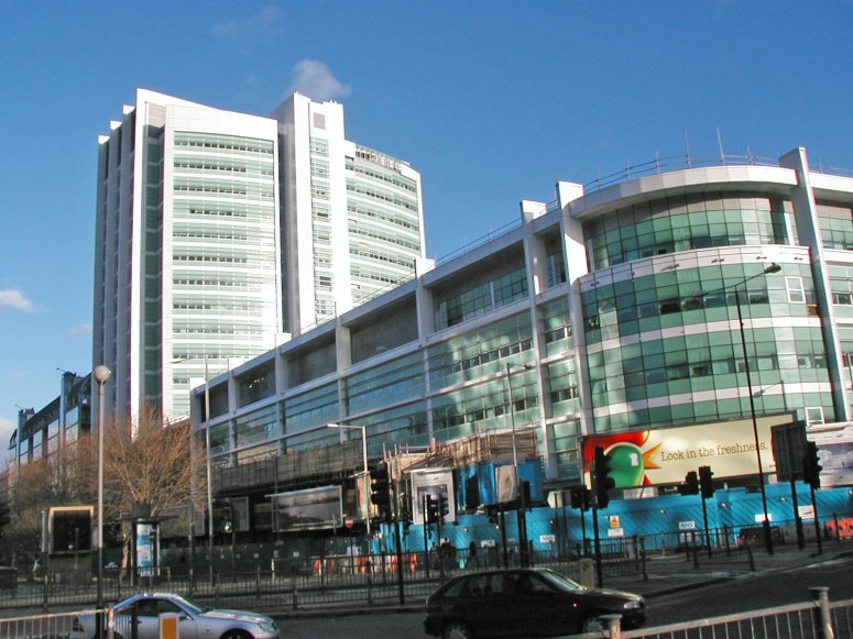
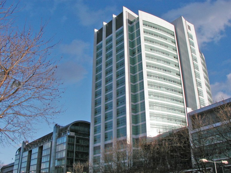 The design and construction
of the new University College London Hospital was undertaken by a joint venture
comprising Amec Group, Balfour Beatty Construction and Haden Young. The first
construction phase, which included a 22 storey tower and a 5 storey adjacent structure,
was completed in 2005. Clarke Nicholls Marcel were responsible for the
engineering design and used LUSAS Consultancy Services to build a 3D model of the 22
storey, reinforced concrete core in order to assess, as accurately as possible, the
interaction between the various core elements which change properties throughout the
building’s height. Gravity loads were applied at the various levels of the tower and
combined with notional horizontal loads also acting at the floor levels. From the LUSAS
analyses, overall wall stresses, local conditions around significant openings and global
tower displacements were obtained and these confirmed CNM’s assumptions of stress
distribution. The design and construction
of the new University College London Hospital was undertaken by a joint venture
comprising Amec Group, Balfour Beatty Construction and Haden Young. The first
construction phase, which included a 22 storey tower and a 5 storey adjacent structure,
was completed in 2005. Clarke Nicholls Marcel were responsible for the
engineering design and used LUSAS Consultancy Services to build a 3D model of the 22
storey, reinforced concrete core in order to assess, as accurately as possible, the
interaction between the various core elements which change properties throughout the
building’s height. Gravity loads were applied at the various levels of the tower and
combined with notional horizontal loads also acting at the floor levels. From the LUSAS
analyses, overall wall stresses, local conditions around significant openings and global
tower displacements were obtained and these confirmed CNM’s assumptions of stress
distribution.
|
Modelling
Six interconnecting sets of jump
formed walls form the central core of the structure.
The walls are predominantly 200mm thick, with a few of 300mm and 400mm thicknesses. In
modelling the core using LUSAS Civil & Structural, 3D thick shell elements
represented the walls. Joint elements were used at each floor level of the core to apply
notional horizontal loadings and also used to specify restraint conditions for the global
horizontal x and y directions in order to 'lock' the structural deformations at each floor
level. These special support conditions required the removal of constraint in the
vertical z-direction for the rigid supports so that the vertical deformations across the
floor plan could vary. Elements in each 'lift' of core wall were grouped together to
allow the display of each core level in isolation to help simplify the model building
process and the viewing of results. In all, over 40,000 thick shell and joint elements
were used to model the core. In addition to the global model of the whole core, local models using solid elements
investigated potential high stress concentrations around selected openings including
service holes and single and double jacking pockets in the 200mm walls.
|
|
|
Loading
Five separate loadcases consisting of core self weight, uniformly
distributed, dead and live loads and a notional load of a specified value acting in North,
South, East and West directions were applied to the model at each floor level. By
combining and factoring these loadcases at the results processing stage nine design load
combinations were formed. From these combinations resultant displacements, in-plane shear
stress resultants and direct membrane stress resultants were obtained for each level of
the core to aid Clarke Nicholls Marcell in their design.
Results
Because of the complexity of the model generated for this project, with
its 9 load combinations, 22 separate floors and large number of walls the output of actual
stresses at top, middle and bottom surfaces of the thick shell elements would have
generated a large number of results plots requiring investigation. So, in order to
simplify the results produced, contour plots of stress resultants were produced instead.
With these the actual stress at a location in a wall is obtained by dividing the stress
resultant value by the corresponding wall thickness.
For
all walls in the core, and under all load combinations, the stress ranges given by the
LUSAS Civil & Structural analysis compared well with those predicted by less
advanced calculation methods. The direct compressive stress resultants confirmed
that the greatest magnitudes were being carried by the thicker wall sections. It was also
found that some of the 200mm walls had significantly higher stress levels than others of
the same thickness. The ability of LUSAS to produce level by level stress results and
highlight disproportionate wall loadings can give useful guidance on the appropriateness
of the wall thickness used for these types of core-walled structures. |
|
|
|
|
John Wilson, Partner responsible at Clarke Nicholls Marcel said: "Although CNM
has a relatively powerful FE capacity in-house we felt it made sense due to the large
amount of data input to use LUSAS to set-up what is a complicated model and analyse it
within a minimum timescale. The results from LUSAS, which were presented with very clear
graphics, enabled us to be completely confident that our assumptions on stress
distribution and hence reinforcement design were correct."
The results from LUSAS, which were presented with very clear
graphics, enabled us to be completely confident that our assumptions on stress
distribution and hence reinforcement design were correct."
John Wilson, Prolect
Partner at Clarke Nicholls Marcel
Find out more
Other LUSAS Civil &
Structural case studies:
|
|
Software Information
|