Case Study
Design and analysis of Gota Tunnel (Götatunneln)
- Detailed 3D modelling of large concrete box tunnel structure
- Creation of customised scripts for results processing
- Smart load combinations and slice sectioning of model
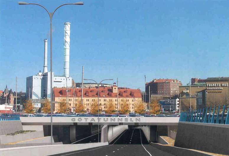
Skanska Teknik AB, of Sweden,
used LUSAS Civil & Structural to help analyse and design a 128m long, reinforced concrete
section of tunnel which carries road 45 beneath the city of Gothenburg. Customised scripts
were developed by LUSAS Consultancy Services for specific use on the project to automate
the results processing operations, produce graphs and screen plots, and output results
data for spreadsheet calculations of reinforcement quantities using Skanska Teknik
AB’s own in-house software.
Overview
The main tunnel design contract
was split into three with the Western cut-and-cover
section at Järntorget being designed by Skanska
Teknik AB. This contract comprised a 96m open cross-section, a 128m long twin
reinforced concrete box tunnel with an integral access ramp structure, ventilation shaft
and 30m high chimney, and a 276m long twin-box tunnel. The 128m long access ramp/tunnel
structure carries two carriageways of traffic in both directions and is also subject to
vehicle loading on its roof due to a car park and access roads above. The tunnel walls and
roof slab are 1m thick. The floor slab varies in thickness from 0.8 to 1.5m. In all,
nearly 1000 piles support the structure.
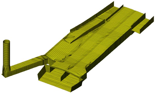
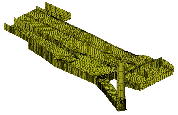
Modelling in LUSAS
Almost 22,000 elements were used to model the complex tunnel structure to the required
level of detail. Thick shell elements - used so that out-of-plane shears could be
extracted - modelled the concrete structure. Joint elements modelled the end bearing and
frictional piled supports.
Load cases applied to the model included:
- Differential settlement, modelled as a sine curve along and across the tunnel centre
line.
- Temperature gradient and shrinkage
- Soil and water pressure
- Varying water level
- Vehicle loads - manually evaluated
ULS
and SLS Load Combinations
In LUSAS, the Smart Combinations facility can automatically generate maximum and
minimum load combinations for any selected design code from applied loadings and allows
for adverse or relieving effects. From these load combinations, envelope, contour and
deflected shape plots and results graphs can be readily obtained for any loadcase under
consideration. However, on this particular project the Smart Combinations facility was
combined with customised scripts written by LUSAS Consultancy Services to automate the
output of the results processing and produce results for additional spreadsheet
calculations.
|
|
|
Scripting in LUSAS
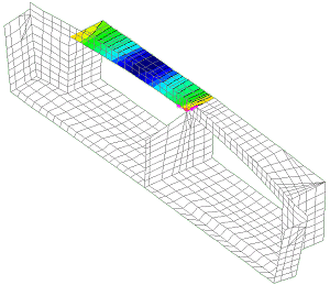
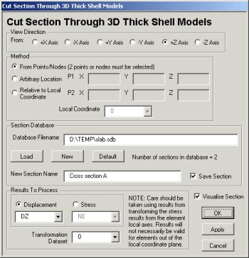
Of many custom scripts written, a model sectioning tool was developed to allow a cut
section to be taken between selected points, nodes or at specified coordinates on the
model. The location of the section could then be stored and named in a database for future
use. Chosen results of interest for the selected loadcase were then automatically plotted
on a corresponding graph. In this way plots of either stress, shear or displacement could
be readily obtained for each active loadcase allowing rapid assessment of the structure
along its length. By changing the active loadcase and re-selecting the same cut name from
the database a whole series of results for the many load cases and load combinations could
be obtained.
To calculate reinforcement quantities Skanska
Teknik AB used stress resultants calculated by LUSAS in its own in-house Microsoft
Excel spreadsheets. A load combination listing script in LUSAS exported basic and smart
load combination definitions and envelopes (including load cases used and load factors
applied) to a spreadsheet for quality assurance, and cross-checking purposes.
|
|
Benefits of using LUSAS
Mathias Uhlán, Structural Engineer at Skanska
Teknik AB said: ‘Since the geometry was so complicated it
would have been difficult to model the tunnel in 2D, and in order to do so a far more
conservative approach would have had to be taken. But by using a 3D
LUSAS model we could slice
sections through the model and easily plot the results we wanted at our chosen
locations.’
He continues:
"Ultimately, the main benefit in using LUSAS for this project was to
be able to take into account the complex geometry of the structure and to
get all of the results we required from the one model."
"...the
main benefit in using LUSAS for this project was to be able to take into
account the complex geometry of the structure and to get all of the
results we required from the one model." Mathias
Uhlán, Skanska Teknik AB
Find out more
Other LUSAS Civil &
Structural case studies:
|
|
Software Information
|