 Case
Study Case
Study
Share this
article
Erection engineering
analysis of a replacement roof for the London Olympic Stadium
-
Erection
engineering analysis for what is believed to be the longest
cantilevered roof in the world
-
Modelling and
analysis of compression truss, columns, cable-net and roof
steelwork using nonlinear methods
-
Structural members of the permanent works and stability of the
structure during roof installation confirmed adequate

COWI (previously Flint & Neill
Limited) was appointed by principal contractor Balfour Beatty to
provide erection engineering services for the deconstruction of the
original roof of the London Olympic Stadium and subsequent
construction of a new long-span replacement roof for what is now
called the London Stadium. This work was required as part of
transformation works carried out on behalf of the London Legacy
Development Corporation. LUSAS was subcontracted by COWI to perform
independent checking of the various deconstruction and construction
stages involved, and confirmed the adequacy of the structural
members which formed the permanent works and global stability of the
structure under applied loads.
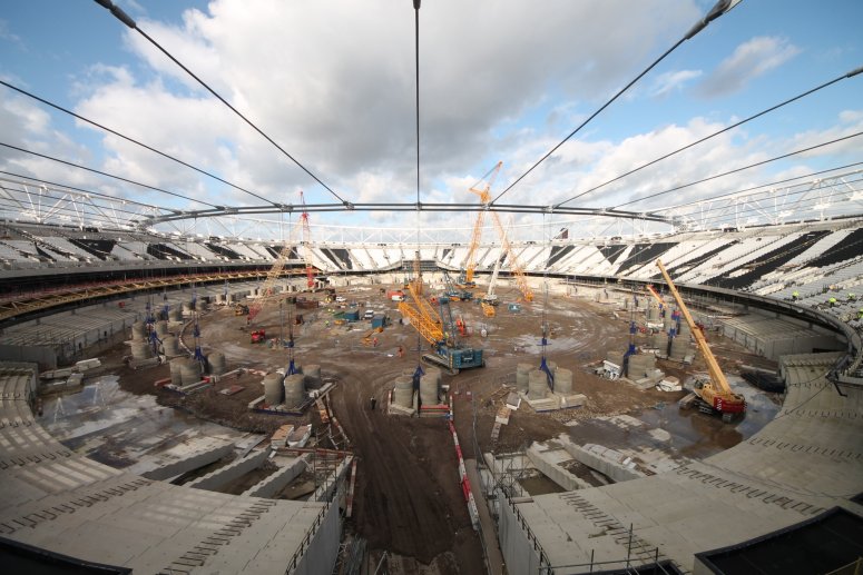
Overview
Subsequent conversion of the stadium
into a mixed-use venue required a new roof to be constructed. COWI
used its own in-house package NODLE to carry out a deconstruction
analysis of the original roof involving dismantling of the lighting
towers, removal of the membrane, and lowering of the cable net, and
roof deconstruction was completed in February 2014. Whilst LUSAS also
carried its own deconstruction analysis of the original roof, this
case study is limited to the erection engineering analysis performed
for the replacement structure.
|
|
|
|
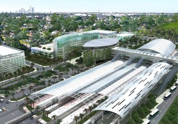
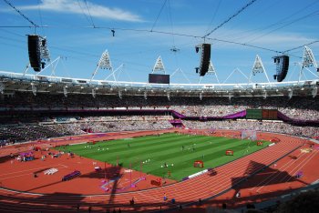
London Olympic
stadium as originally constructed.
|
Original stadium
roof.
|
|
The new roof
consists of a primary cable net structure supporting
articulated steel trusses which create the upper roof
profile and in turn support the roof coverings. The existing
compression truss connections and raked V-columns required
strengthening to bear the increased loading from the new
roof structure which, at approximately 48,000 square metres,
and with a maximum cantilevered length of 84m, is twice the
area and three times the span of the original.
The
construction sequence and hence modelling and analysis
requirements for the new roof took place in
three distinct phases:
-
Phase
1: V-column strengthening / replacement
-
Phase
2: Installation of cable net
-
Phase
3: Construction of rear and front roof
|
|
|
New and
original roof configuration.
|
|
|
|
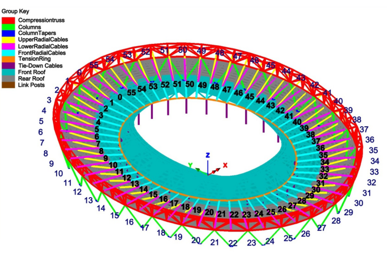
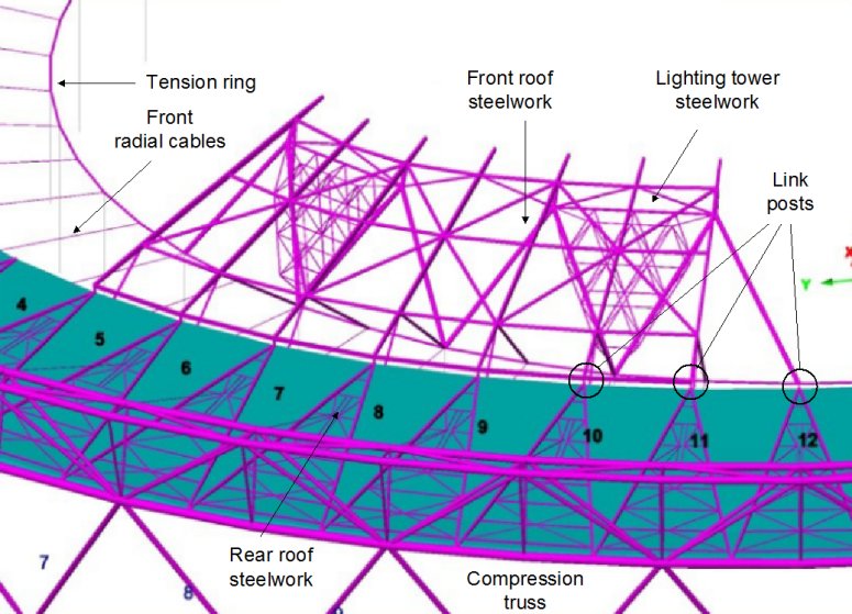
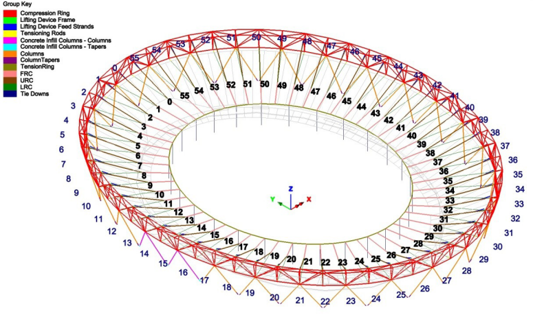
Key components
of the new London Stadium roof.
|
Overall analysis
and modelling requirements
LUSAS was required to verify the
adequacy of the global structure and structural members at critical stages of construction. This involved:
-
Ensuring that the
starting LUSAS finite
element model (used in a reverse analysis) satisfied the reference stressed state reflecting the permanent condition of the
completed stadium roof.
-
Analysing the staged replacement of
the V-columns and providing an envelope of member forces on connections for
use and verification of local connections by others.
-
Analysing the roof structure at various
stages in order to verify that all structural
members designed for permanent condition were adequate for the
proposed construction methodology and that structural stability
was
maintained throughout.
-
Providing internal forces, enveloped
erection force effects and utilisation factors for critical
members in the roof members, cables, compression truss and column structure
for various stages of the construction process; and displacements at
key locations for various stages.
In all analysis cases, the LUSAS models
generated were subjected to loads based on British Standards as
appropriate to the structure and its location. Generally:
-
The compression truss and columns of
the stadium were modelled and analysed using appropriate large
displacement nonlinear methods, using thick nonlinear beam elements
in which shear deformations were included.
-
Cables were modelled using multiple
elements to distribute self-weight loading along their lengths,
and to include
the geometrically nonlinear effects of the cables sagging. Cable
element end releases permitted free rotation at the cable
connections, and a low bending stiffness along with using
nonlinear joints at their end allowed the cables to behave as
tension-only members.
-
Beam end releases were used to
model the individual connection requirements for each
member.
-
For modelling and
analysis of all construction phases extensive use was made of
LUSAS Visual Basic scripting facilities to automate procedures
such as loading assignment, creation of load combinations, and
the carrying out of design checks.
Phase 1
- V-column
strengthening / replacement
|
This required
the strengthening and replacement of the
original raked
V-columns.
Replacement of
the original raked V-columns was simulated using a
geometrically nonlinear static analysis to take into account
the effects of the changes in position and angle between
column and truss members. To model each column
replacement, first, the
support at the bottom of the adjacent column (which was not
being removed) was changed to be pinned and the framing-in
column removed. Then, a total imposed displacement load was
applied to the upper node of the removed column to return the deformed mesh to its
original position (modelling the jacking-up process). A new
column was then activated with pinned supports. Removal of jacking
simply required removal of the imposed displacement, before
permanent loading only was re-applied to reinstate the original loading conditions.
Member
resistances/utilisations were calculated using
BS5950-1:2000 for all members in the compression truss using
the appropriate section properties. To do so, two global models were
developed; one having diagonal members of the compression ring pinned about both axes of rotation
such that end moments would be zero, and the other with diagonal and
radial members pinned about one axis and rigidly fixed about the second.
For summarising truss connection force envelopes, the fully pinned
model was used, but for all other results the model with one
fixed end condition was used.
Results
obtained
Checks carried
out for Phase 1 included those
appropriate for shear, moments, axial tension/compression
and combined effects as appropriate. Results plots and
spreadsheets of utilisation factors for all truss members
and loadcase combinations based on design code were obtained
and confirmed the adequacy of the permanent
works and the stability of the structure during column
replacement.
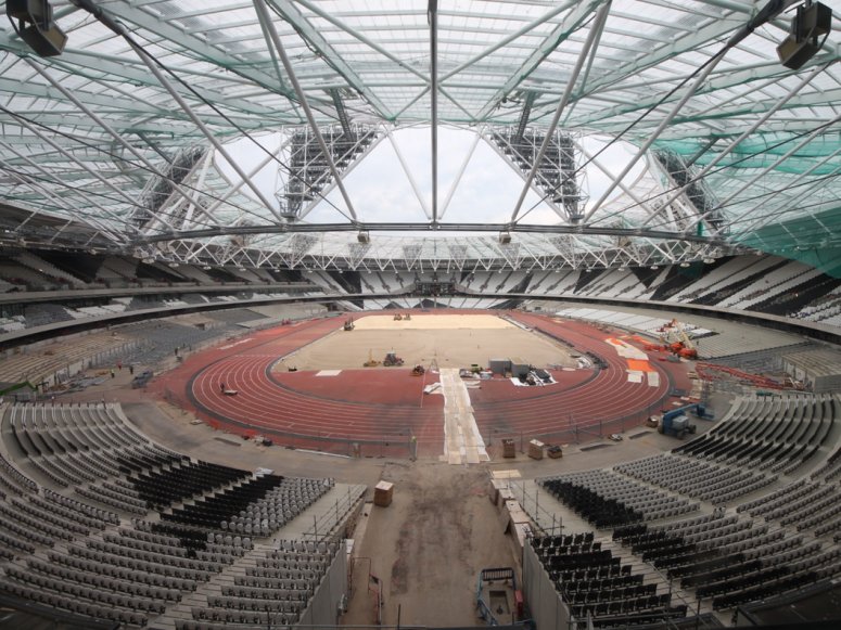
|
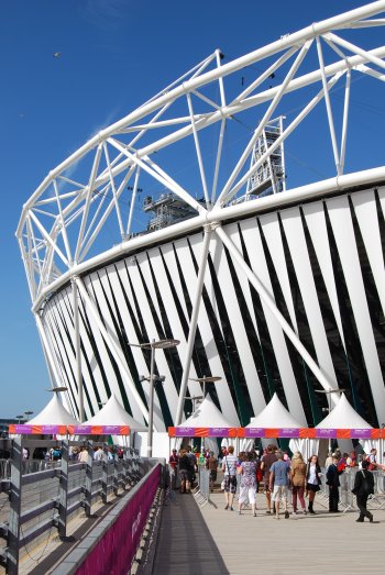
London
Olympic Stadium as built, in 2012
|
Phase 2
- Installation of cable-net
The tension ring was
lifted into place by using strand jacks installed on the inner top
chord of the compression truss. This was followed by installing and
stressing the lower radial cables using hydraulic jacks. Temporary
tie-downs were installed to pull the tension ring into a predefined
geometry.
|
|
|
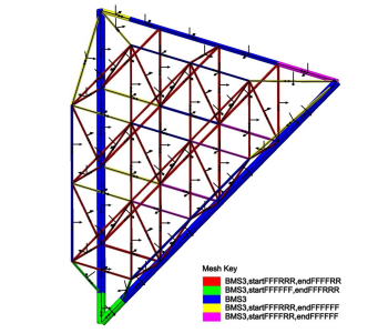
LUSAS model
for Phase 2 analysis. |
Modelling
and analysis
The initial lay-out positions on the
ground for the lug plates and tension ring connectors were one of
many items to be
determined as part of the Phase 2 analyses. From inspection
of the roof geometry and member connections to be used when
modelling the construction of the rear roof (Phase 3A), it was seen that a
reverse construction (deconstruction) modelling approach could be
taken, and this was critical to being able to start the analyses
from the supplied reference condition for the final form of the
structure. As a result, the lifting and stressing analysis was
therefore carried out in a reverse order starting from the end
of the
stressing phase, and modelling the lowering of the cable net system
until the cable-net lug plates and tension ring connectors had come
to rest on the seating tiers and the ground. Joint elements with
nonlinear smooth contact properties were used at the intermediate
nodes and tension ring nodes to model contact in a direction normal
to the ground and upper or lower seating tiers as appropriate.
The
bases of the V-columns were
modelled as pinned during the stressing phases. At the end of the stressing phase
the bolts at the bases of the columns were fully tightened and these
were modelled as fully fixed in translation and rotation from the
end of the stressing phase and during the tying down and roof
steelwork erection phases. The Upper Radial Cables (URC), Lower Radial
Cables (LRC), Front Radial Cables (FRC), tension ring and lifting
device feed strands were modelled in LUSAS using multiple thick
nonlinear beam elements with end release to allow free rotation at
the cable connections. Cables were modelled with multiple
elements to include
the geometrically nonlinear effects of the cables sagging. Lug plates at
intermediate nodes and the tension ring connectors were modelled as
a single node with their self weight applied as a concentrated point
loading at each appropriate location. Tie-downs were modelled using
a single bar element per tie-down. Tie downs (without any anchorage)
were to be allowed to lift with the tension ring, and as a result
the weight of these tie downs and their connections was modelled as
a concentrated load at each tie down location. For anchored
tie-downs, the weight of each kentledge was applied as a
concentrated load at the supported point at the tie down location in
the model, to allow reactions to be checked more easily.
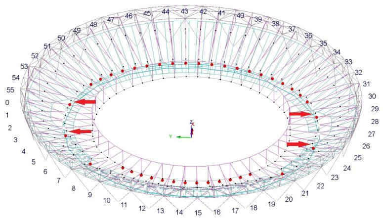 |
| Cable-net
lift (red circles show contact locations). |
| |
 |
| Animation
of cable-net
lift: aerial view. |
| |
 |
| Animation
of cable-net
lift: view along y-axis. |
| |
 |
| Isolated
animation of cable-net lifting at grid line 0. |
| |
 |
| Cable-net installation
and tie-down complete.
|
Results obtained
For Phase 2, LUSAS provided the
following results from global models of the new roof for various
stages of the cable-net installation process:
- Cable forces and angles
- Utilisation factors for all truss members, columns and cables
- Forces applied indirectly to the
seating tiers
- Feed strand lengths during the
lifting phase
- Verification of the stress free
layout geometry of the cables, lug-plates and tension ring
- "Lift-off" position of
each lug plate and ring cable connector
- Verification of the geometry at
the end of the lifting, stressing and tying down phases
- Verification of the target
geometry and tie-down tensions at the end of tie-down
- Verification that the safety
factor against kentledge lift-off was adequate
Phase 3
- Construction of rear and front roof
In
Phase 3, roof erection started with the installation of the rear
roof and on two construction fronts, with the installation of
the rear roof cladding following one-eighth behind the
construction fronts. Once the main steelwork and three-quarters
of the rear roof was clad the erection of the front roof
started, with its associated lighting towers and cladding
following a similar sequence. To aid the erection process to
achieve the target roof configuration, temporary link posts were
installed at the apex of the rear roof back diagonal beams where
the rear and front roof were temporarily linked. The outer ends
of the front radial beams were connected to these to allow the
front roof to be held as further elements were installed.
Using LUSAS Civil & Structural a
geometrically nonlinear static forward analysis was carried out to take into
account the effects of the changes in position and angle between
members and to account for nonlinear effects in cables. The column, truss
and cable net configuration was inherited from the Phase 2 analysis, so that identical stressing and tie-down stages
could be incorporated into the Phase 3 analyses, and additional steelwork and cladding of the
front roof was
incorporated into the analysis.
When modelling in
LUSAS, the link posts were considered to be very stiff to obtain the
forces-moments in these members and ensure that the correct relative positions of the rear and
front roofs were maintained. These link posts, along with the tie-down
cables installed in Phase 2, were removed once the roof erection
process was complete. By using a forward construction analysis as
opposed to a reverse one, after
removing the link posts and tie downs the circumferential beams of the front
roof steelwork would be in axial compression on completion, and a
predicted constructed geometry would be obtained.
|
|
|
Modelling of
rear and front roof erection sequences.
|
| |
 |
| View
of rear and front roofs showing upper, lower and front
radial cables connecting to lug plates and tension ring. |
Results obtained
For Phase 3, numerous results from
global LUSAS models of the new roof were obtained to check the various
stages of the roof steelwork installation process. These included:
-
Utilisation factors for
all truss members, columns, cables and roof steelwork
-
Link post forces and moments under
SLS and ULS loading combinations for the whole erection of the front
roof
-
Connection forces for the connection
of the rear roof back diagonal beams to the compression truss,
which are affected by the temporary connection of the front roof to the
rear roof through the link posts during the erection of the front
roof
-
Verification of the geometry at the
end of each notional erection stage
-
Estimation of the lack of fit
adjustment to the circumferential members
-
Verification that the kentledge, used
to hold down the tension ring,
would not lift-off during the erection process
|
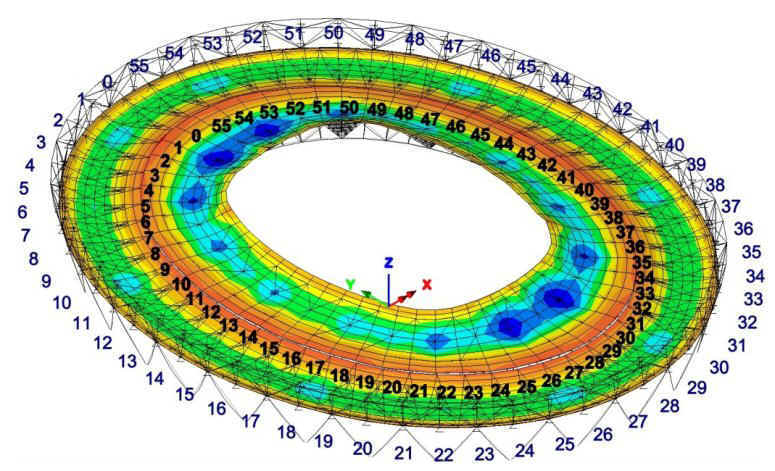
|
|
Vertical displacement
contours for final roof position (for cladding speed case
1). |
|
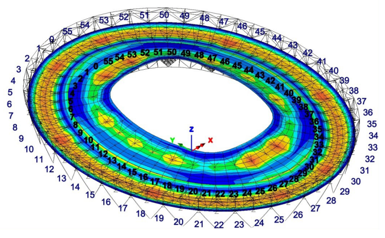
|
|
Resultant
displacement contours for final roof position (for cladding speed case
1). |
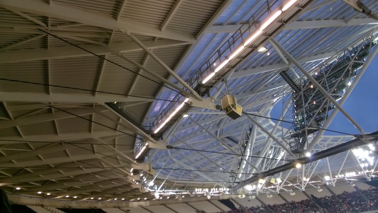
Summary
The transformation of the former London
Olympic Stadium into what is now known as the London Stadium is now
complete, and its replacement roof is believed to be the longest
cantilevered roof in the world. From 2016 it became the new home for
West Ham United Football Club, and the National Competition Centre for
athletics in the UK.
|
|
|
Roof erection
completed.
|
|
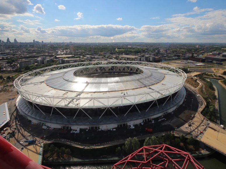 |
|
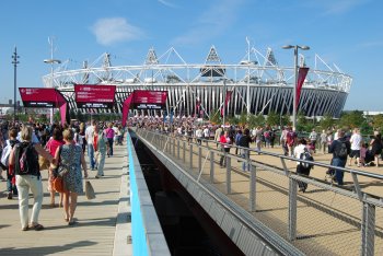
As viewed from the
adjacent ArcelorMittal Orbit structure in Queen Elizabeth
Olympic Park.
|
Project team
-
Principal contractor:
Balfour Beatty
-
Structural engineer:
Buro Happold
-
Erection engineer:
COWI
-
Steelwork
subcontractor: William Hare Limited
-
Cable-net
subcontractor: Pfeifer
-
Cladding
subcontractor: Lakesmere
-
Architect: Populus
"The use of LUSAS VB
Scripting techniques to customise the software and to automate the extensive
modelling and checking procedures required, allowed us to save a great
deal of time and ultimately confirm the
adequacy of the structural members which formed the permanent works
and global stability of the structure under the applied loads."
Dr Ahad Kolahi,
Project Manager, LUSAS
Share this
article
Find out more
Other LUSAS Civil &
Structural case studies:
|
|
Software Information
|