Case
Study Case
Study
Share this
article
Design of canopy
structures for Miami Central Station
-
Elliptical steel
arch canopy for Miami
Airport Metrorail Station
-
Moment resisting
steel frame for an access/entrance canopy
-
Aerofoil-like bus
station canopy
Miami
Airport Metrorail Station, designed by architects and planners Perez
& Perez, is the first main component being built for the Miami Central Station in Florida.
Genesis Structures used LUSAS finite element analysis to assist with
its design of a variety of canopy structures and roof panel components
for the project on behalf of its client, internationally acclaimed
engineering and fabrication company, Zarner.
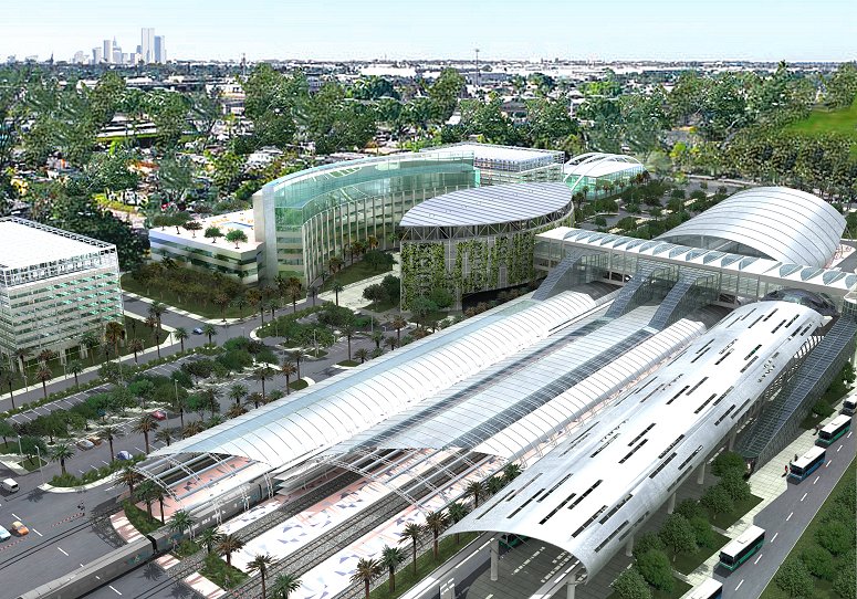
Overview
Located next to the Miami International
Airport, the Miami Intermodal Center is a massive ground
transportation hub being developed by the Florida Department of
Transportation. The Miami Central Station forms a major part of this
development that, when complete, will connect the various
transportation systems of Palm Beach County, Fort Lauderdale, Miami,
and the Florida Keys.
Zahner was awarded
the construction contract for the engineered roof system for the main
canopy of the Metrorail Station, the South canopy and the bus station
canopy structures. Genesis Structures was selected by Zahner to
provide structural and erection engineering services for this work.
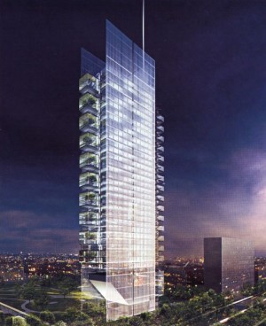
Metrorail Station
Canopy
The slotted canopy of the Metrorail
Station is the most prominent feature in the station complex. With a length of
nearly 500 feet, the structure consists of eleven structural steel
ribs, each of an elliptical profile, that are connected via baseplates
to an in-situ concrete framing support system. In designing the ribs
Genesis worked closely with the steelwork fabricator Columbia Wire
& Iron to develop details that accommodated their preferred
fabrication methods. Specially designed structural aluminum roofing
panels span between ribs to provide protection for the station
concourse.
|
|
|
|
Rendering of the
Metrorail Station structure |
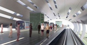
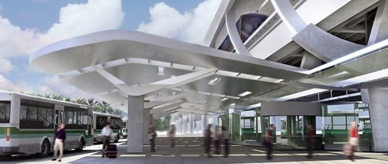
Rendering of the inside of the
Metrorail Station |
Perez & Perez�s design of the
canopy called for a planar roof structure that twists along the
horizontal axis of the canopy. This roof structure was designed with
Zahner as a structural aluminum box system approximately 60 inches in
depth, spanning approximately 43 feet, with full-depth slots to allow
natural light penetration into the station beneath.
|
|
|
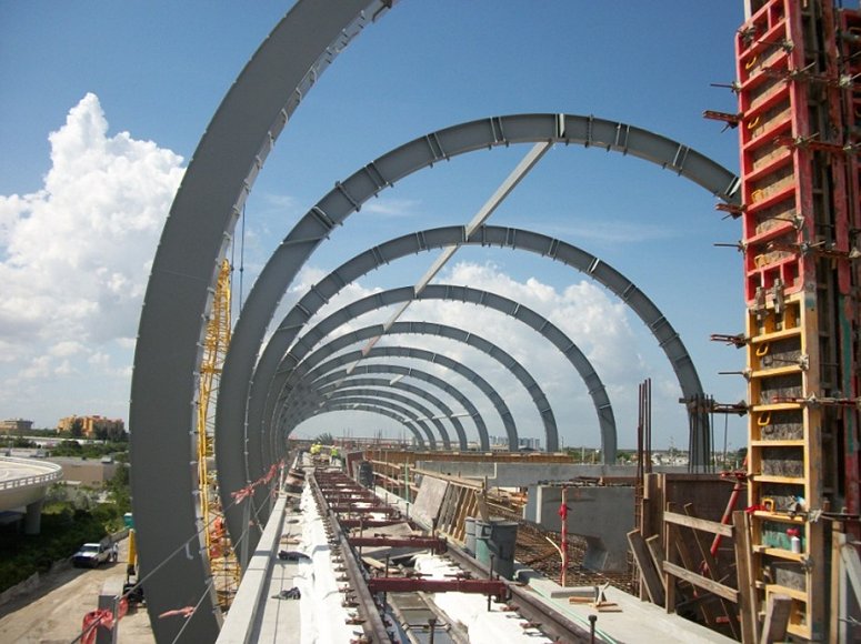
Erection of
elliptical steel arches for main canopy |
|
|
|
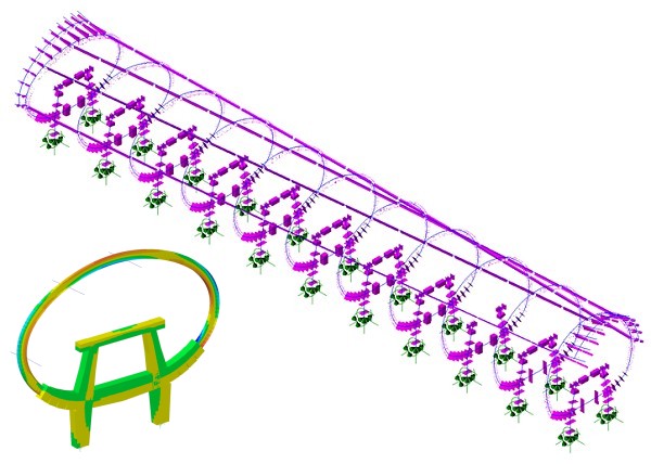
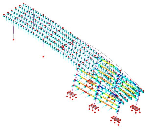
LUSAS modelling
of Metrorail Station structure |
South Canopy
The South Canopy contains elevators,
stairs and escalators which provide access from ground level to the
main canopy. It is designed as moment resisting steel frame supporting
the aluminum wall and roof panel system.
|
|
|
LUSAS model of
South Canopy |
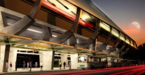
Bus Station Canopy
The
aerofoil-like Bus Station Canopy structure provides access to
the main transportation hub for bus passengers. It consists of
a structural steel frame covered with full-depth aluminum roof
panels clad in a propriatory stainless steel finished skin.
Its design required careful coordination between Genesis
Structures and the engineer of record for the lower portion of
the Main Canopy due to the partial support conditions
provided. Special evaluation of wind loading on the large
horizontal surface was also undertaken and coordinated with
the wind consultant, RWDI.
|
|
Rendering
of Bus Station Canopy |
|
|
|
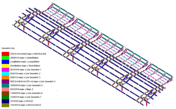
LUSAS model of
Bus Station Canopy |
Roof panels
Designing the various roof panels for
this project presented a particular challenge. Because of the station�s
location the structural components are subject to some of the most
severe wind loading in the United States. From scaled wind tunnel
analysis performed during the preliminary design phase of the project,
design wind pressures were arrived at for use on the structural and
cladding portions of the structures. The maximum design wind speeds of
150 mph that were used generated design cladding pressure loading of
nearly 130 pounds per square foot. LUSAS models of representative
panels were built and used to assess deflection and other criteria.
|
|
|
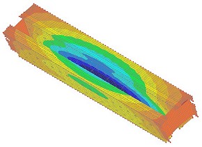
| LUSAS
model of typical roof panel |
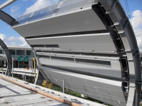
First roof
panels in position on the main station canopy |
"We used LUSAS to model all
components of the Miami Airport Metrorail Station structures that we were
involved with. It allows easy importing of complex geometry models and
lets us apply all code-required load combinations in a very
straightforward way."
Dave Byers, Principal, Genesis Structures
Share this
article
Find out more
Other LUSAS Civil &
Structural case studies:
|