|
||||||||||||||||||||||||||||||||||||||||||||||||||||||||||||||||||||||||||||||||||||||||||||||||||||||||||||||||||||
Various load combinations needed to be assessed using LUSAS. These included permanent actions comprising load from the surrounding rock, self weight, water pressure and support displacement. Variable loads comprised traffic loads, water level variations and change of temperature. Accidental actions considered a variety of potential ship impacts and large-scale shifting of the bedrock.
Modelling CAD model geometry representing a 70m long x 80m wide x 50m high volume of rock and tunnel was imported directly into LUSAS prior to defining the material properties, supports and various loading conditions that needed to be assessed. The rock and the concrete tunnel connector were modelled using 20-noded volume elements. Bar elements represented the longitudinal and transverse anchorage cables. Joint elements modelled the contact between the rock and the tunnel and allowed frictional forces between these to be taken into account. To verify the model built, the coefficient of friction at the contact surfaces between the concrete tunnel and the rock was set to zero and a single load case with just the anchorage cable tensions was applied. From this, initial stresses in the rock around the anchorage points, and stress transfer and stress levels in the concrete and the rock heel could be evaluated. Because of the interfaces used in the model a nonlinear analysis had to be undertaken.
Accidental loading For a number of the accidental loadcases considered, different coefficients of friction for the contacting concrete tunnel and rock surfaces were used to evaluate the effect on the results obtained. The effects of a horizontal or vertical displacement of the main tunnel, both of which apply a torque to the connector, and a longitudinal pulling force on the connector itself were examined in great detail, with stresses in the rock and anchorage cables, and stresses in contacting regions of the concrete and the rock being of particular interest. Displacement and stress distributions calculated by LUSAS for these various loadcases and combinations were plotted on a number of slice sections through the model. In addition to slice sections at and in the vicinity of the cable anchorage points, horizontal sections were located at the mid-height of the tunnel, and at distances of 4.5m, 10m, and 15m below the tunnel base. A longitudinal vertical section and a slice section inclined at 15 degrees towards Söderström (north) and 15 degrees to the east (to correspond with a fracture zone in the rock) enabled a detailed comparison to be made between the results from the LUSAS analysis and analytical results by others. Representative Results Plots The following images illustrate the types of results plots created to evaluate the magnitude of stresses and forces at the connection, in the anchorage cables, and in the rock itself due to permanent, variable and accidental loading to the immersed concrete tunnel.
In Summary The results obtained with LUSAS showed that the tensions and deformations arising in the rock from the applied loading to the tunnel connection were reasonable taking into account the friction between the concrete tunnel and the rock. The forces in the anchoring cables for both the rear anchor and cross anchorage were shown to increase slightly as a result of accidental loadings. This increase was greatest in the transverse anchors but did not exceed 10% of initial prestressing force. Overall, the results indicated that the concrete tunnel connection will remain stable for all analysed loading conditions. Other links
Share this article
Find out more
Other LUSAS Civil & Structural case studies:
|
|
Software Information
|
||||||||||||||||||||||||||||||||||||||||||||||||||||||||||||||||||||||||||||||||||||||||||||||||||||||||||||||||||
|
||||||||||||||||||||||||||||||||||||||||||||||||||||||||||||||||||||||||||||||||||||||||||||||||||||||||||||||||||||
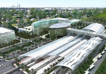
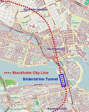 The Stockholm City Line is a 6km
long
commuter train tunnel running beneath central Stockholm, with two new
stations at Odenplan and T-Centralen. It is being built by the Swedish
Transport Administration in close co-operation with the City of
Stockholm, Stockholm County Council and Stockholm Transport, SL. When
finished in 2017 the new line will
double the capacity for rail traffic through the centre of Stockholm
The Stockholm City Line is a 6km
long
commuter train tunnel running beneath central Stockholm, with two new
stations at Odenplan and T-Centralen. It is being built by the Swedish
Transport Administration in close co-operation with the City of
Stockholm, Stockholm County Council and Stockholm Transport, SL. When
finished in 2017 the new line will
double the capacity for rail traffic through the centre of Stockholm