 Case
Study Case
Study
Raising
the roof of the Chunju/Jeonju sports stadium
- global modelling of stadium roof structure
- development of cable stay tensioning sequence
- linear analysis
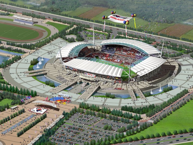
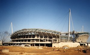
Tony Gee & Partners were retained by steelwork fabricator/erector Hanmaek Heavy Industries Co Ltd
to provide a full erection analysis of the 260m x 160m roof
structure of the 42,000 seat Chunju/Jeonju sports stadium, one of 11 new stadiums
being constructed in Korea for the 2002 football World Cup. TGP's
brief was to define the cable prestressing sequence and the values of prestress to be used
at any given time. The aim was to be able to predict on site and in advance the effect
that tensioning any one cable, or pair of cables, would have on any other cable. TGP chose to use
LUSAS Civil & Structural analysis to help model the construction process
and built a LUSAS model of the complete roof structure
including masts and stays.
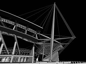
Chunu/Jeonju stadium has a
steel roof comprising a perimeter truss supported on A-shaped columns to the rear of the
grandstand and an inner ring truss supported via a fanned cable network on four, 63m high
masts. Because all cable stays have an influence on all other cables
attached to that mast the sequence of stressing the cables and raising the roof from its
erected position was of vital importance to achieve both the correct roof shape and to
avoid any unacceptable locked in stresses.
To simplify the modelling of the 20000 sq. m. space frame roof, models
of individual roof trusses were created to provide equivalent section properties for a
single beam element for use in the main model. Bar elements modelled the cable stays.
Pinned supports were used at the base of the masts. Spring supports modelled the
supporting columns of the pre-cast concrete grandstand around the perimeter. Plain
vertical supports were used at each of the 32 trestle positions where lift-off would
occur. Whilst a nonlinear analysis with lift-off joints could have been carried out
considering catenary effects TGP made a conscious decision to perform a linear analysis
and evaluate support lift-off by using an inspection method. As final tensions are
approached the cable extensions approach the modelled linear behaviour.
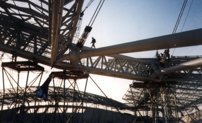
| At each mast 7 cables support the free edges of adjacent roof sections (4 on
the long section, 3 on the shorter section). In addition, 4 cables arranged in a diamond
shape in the plane of the cross beam between adjacent roofs, anchored at the same position
as a pair of cables from the ring truss, together with another pair going out from the
roof to the branch beam at the rear of the mast stabilise it laterally. Cables used are
typically of 65mm and 95mm diameter. The main rear guy at a mast consists of 6, 100mm
diameter cables and carries in excess of 1000 tonnes. |
|
A key part of the analysis was to investigate whether progressive
tensioning all of the cables in one corner could be achieved without affecting other
cables in other corners prior to moving to another corner to repeat the sequence. This had
obvious construction benefits in avoiding the need to move the tensioning equipment around
the site. To test for this, temperature loadings were applied to model the tensioning of
each cable individually. Also, as a check, a unit load was applied to each cable in turn
to see what tensions and compressions it put into other cables (for one corner only). From
these results a matrix was produced which could then be solved for any cable tensioning
sequence.
| David
Barnes, Associate at TGP, explains: 'We looked at each cable in turn because you could
work out what the effect of stressing two cables at once would be by adding the columns in
the matrix together. A unit load was applied to each cable at one corner to work out what
effects that had on all other cables in that corner. We also looked at whether tensioning
one corner would have any effects on cables in the other corners and found that the load
transfer was negligable (less than 2.5%). Therefore the 3D unit in each corner was
effectively self contained and could be stressed independently of the others.' |
|
The inner ring truss is so stiff
that the cables fanning out from
the corner do progressively less and less work and the longest cable is almost
architectural in nature. As a result, tensioning the main load-carrying
cables cables in the corner slackens off the wide fanning cables and leads to a continual
change of tensions throughout the cable system. The permanent works designer had given TGP
a set of final cable tensions that had to be obtained on site and the matrix was solved to
achieve these. Simon Dimmock, engineer on the project said: 'In tensioning the cables on
site we were always going to have a situation where the last cable to be tensioned would
affect all the others, so we had to know what that effect was in
advance - hence the use of LUSAS'. Multiple LUSAS analyses were carried out starting with the roof sitting
on the trestles with no cable tension, before increasing the tension in two cables at a
time up to 25% tension. After all cables had reached this level of tension the sequence
was repeated using tensions of 50%, 75%, 90% and finally using 100% of the tension
supplied by the permanent works designer.
This tensioning sequence was used by Tony Gee &
Partners on site. Because of the linear analysis approach and the absence of modelling the
catenary effects the response of tensioning the cables on site to 25% of final tension did
not reflect the response suggested in the LUSAS model. Later tensioning to 90% and above
matched the LUSAS model far better. The philosophy of the permanent works design was that
once the correct tensioning was applied the roof would simply lift off the trestles -
which it did. Using LUSAS, lift off was estimated to occur at between 80-90% of final
tension and in fact the corner lifted off very slightly before that. Whilst TGP was not
doing a third party check, the process of creating a separate computer model with LUSAS
and having the roof lift off the trestles when the tension specified by the permanent
works designer was input, effectively corroborated their work.
"In tensioning the cables on
site we were always going to have a situation where the last cable to be tensioned would
affect all the others, so we had to know what that effect was in
advance - hence the use of LUSAS."
Simon Dimmock,
Project Engineer, Tony Gee & Partners
Find out more
Other LUSAS Civil &
Structural case studies:
|