Case Study
'The Sentinel' - a
Spitfire sculpture
-
Linear static, buckling and frequency analysis of a steel and
aluminium sculpture
-
Self weight and wind loading assessment
-
Calculation of stresses and optimisation of plate thicknesses
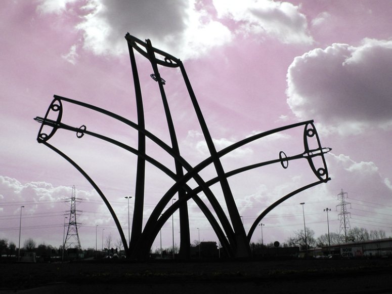
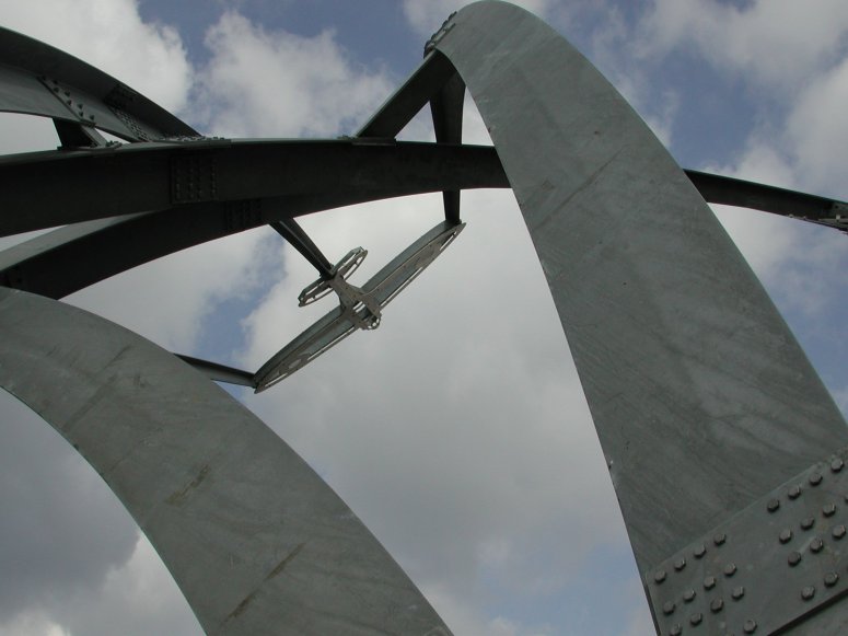
"The Sentinel" is an award winning 16m high sculpture in
Birmingham, UK, consisting of 3 half-scale aluminium Spitfires peeling-off in different
directions and supported by curving steel "vapour trails". It captures the
dynamics of the Spitfire in flight and commemorates the nearby Castle Bromwich factory,
which now produces Jaguar cars, where most of Britain's wartime Spitfires were built. Maunsell was appointed to design the sculpture and
used LUSAS Civil & Structural analysis software to optimise member sizes and
help turn the artist Tim Tolkein's vision into reality.
Maunsell's
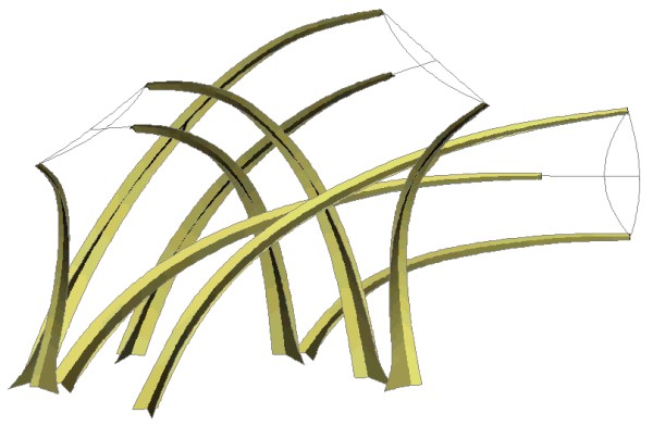
initial discussions with the artist resulted in a tapering curved tee section being chosen
for the vapour trails. A LUSAS 3D beam model of the sculpture was created initially to
determine a first estimate of the load effects, and give preliminary sizes for the
members. From this, a more accurate 3-dimensional CAD drawing of the sculpture was
created. In doing so, a great deal of effort was required to balance the geometry of the
sculpture. The trails had to pass close enough to allow interconnection in some cases,
while avoiding clashes between others. Conflicts between the bases also had to be avoided.
All these factors had to be considered while at the same time maintaining the artists
original idea of dynamism.
Due to the complex shape, and the high slenderness of the beams, it was not
possible to use design codes for the structure. Initially, attempts were made to apply
British steelwork design codes (both BS 5400 and BS 5950), however it soon became apparent
that this structure was beyond their scope of application. Estimates of effective length
and slenderness varied widely, not only between the different design codes, but also with
different interpretation of the clauses. A detailed LUSAS analysis was therefore required
that would not only determine the complex interaction between the elements of the
structure, but would also be able to determine the nature of the buckling behaviour of the
structure. In addition, an accurate calculation of the natural frequency of the structure
was required to assess its behaviour in wind.
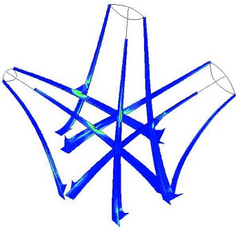
Using LUSAS, subsequent linear static, buckling and frequency analyses
were performed using a more detailed 3D thin shell model. These analyses helped to fine
tune member and plate sizes, establish buckling modes, and factors of safety against
buckling, and also to establish the natural frequency required to determine the behaviour
in wind, which was the main structural concern.
Wind loading
|
Two alternatives were available to
determine the effect of wind loads on the structure. Wind tunnel testing was considered as
expensive and perceived to be of limited value, as it would only give an indication of the
possible effects but no definite results. The chosen option was to use the wind code BS
6399 and approximate the sections required.
|
BS 6399 is essentially a method for analysing structures which are
regarded as static. In order for this code to be applicable the classification factor Kf
must be less than or equal to zero. When Kf is between 0.1 and 2.0 it means the
structure is mildly dynamic The static analysis can still be used but a dynamic
magnification factor is applied. Above a value of 2.0 the structure is not stiff enough to
be assessed by static methods. The classification factor is, amongst other factors,
dependent on the natural frequency of the structure. In order to be able to use BS 6399 a
natural frequency above 1.0 was required. |
The natural frequency analysis showed
where the structure could be stiffened so that a static analysis could be used to quantify
the wind forces. This was achieved by increasing the section size of the spitfire
sub-frames and adding cleats between passing trails until the natural frequency of the
structure was sufficiently high (approx. 1.33Hz). Bolted connections were chosen as they
provide better damping characteristics than welded connections.
Buckling
With a satisfactory natural frequency determined, the wind loads could be
calculated and the structural analysis could continue. As design codes do not exist for
such a structure, the sculpture had to be designed from first principles. The buckling
analysis included calculation of the local stresses in the steelwork and calculation of
the dynamic buckling effects. An eigenvalue buckling analysis was used to determine
the buckling capacity due to self weight and applied wind loads. The graphical output from
LUSAS Civil & Structural allowed easy viewing of the mode of failure and any
weaknesses to be examined. In early analyses, the structure's first buckling mode occurred
in the sub frames. These sub frames hold each cluster of trails together and support the
aluminium plane silhouettes. A value of >2.5 was selected for the target load factor
for buckling. However these first attempts provided a value less than 1.0, so the section
size of the sub frame was increased and the buckling modes were transferred to the trails.
The thickness of the base sections of the trails was increased and more trails were
interconnected. These strengthening measures increased the lowest load factor for buckling
to above 3.5 with a corresponding natural frequency of 1.34.
| Nick King, the checking engineer on the
project, said: "LUSAS Civil & Structural allowed a safe design to be
realised within very tight budget constraints. The ability to rotate, zoom in and out,
define groups, contour results, and animate the mode shapes all made the visualisation and
understanding of the results relatively simple. Pages of numerical output would have been
completely meaningless. Without an analysis package such as LUSAS, this project would
probably not have been built with any degree of confidence". He
continues: "We refined the structure as much as possible without
employing a full non-linear buckling analysis or wind tunnel testing techniques, but with
more time and budget, it would have been beneficial to reduce the number of cleats
required, and to reduce the size of the sub-frames. To do this we would have used the full
geometric and materially non-linear buckling analysis capabilities of LUSAS".
|
|
"LUSAS Civil & Structural allowed a safe design to be
realised within very tight budget constraints...without an analysis package such as
LUSAS, this project would
probably not have been built with any degree of confidence".
Nick King, Project
Engineer, Maunsell
Find out more
Other LUSAS Civil & Structural case
studies:
|
|
Software Information
|