|
||||||||||||||||||||||||||
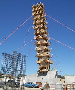
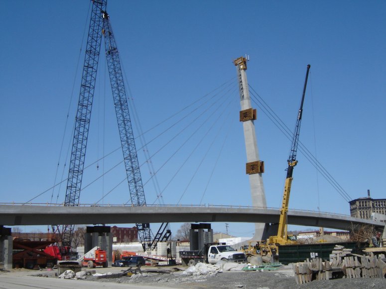
Pylon
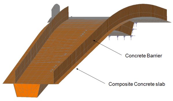
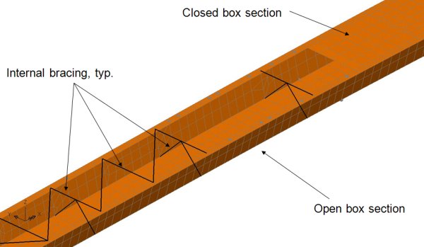
Superstructure and supports The steel plates, stiffeners, composite concrete slab and concrete barriers of the superstructure were all modeled using 3D shells. Internal girder bracing was modelled with beam elements. Time-dependent (creep and shrinkage) effects on the concrete slab were also included. The concrete deck pours required temporary bearings to be used initially at the abutments (and on the model) to allow for beam rotation. Then, once the integral abutment connections were made, the modelled supports were updated accordingly. The eccentric cable loading on the box girder system produces torsion and lateral thrust in the girder. This is resisted by upward, downward, and lateral bearing supports at the abutments and by tension linkages and vertical and lateral bearings at the pylon support strut. Three falsework towers that supported the west span were modelled using compression-only supports that allow accurate modelling of the lift-off behaviour due to cable tensioning.
Cable installation and post-tensioning Cable installation and stressing were carried out in a balanced manner and to forces defined by the proposed erection sequence. Some stays required only a single jacking operation while others required two jacking operations at different construction stages. As the installation and stressing of the permanent stays progressed, the temporary pylon guys were removed. Progressive installation of cables and post-tensioning of the pylon caused a gradual decrease in reactions and eventual lift-off at the falsework supports. A 30-year creep analysis carried out at the end of the staged construction process evaluated long-term effects on the structure.
Design limitations The contract documentation placed design limitations on the pylon restricting the horizontal displacement at its top to two inches and also restricted the maximum amount of bending moment about its weak axis at a specified level at its base to be 800 kip ft during its construction, unless any exceeded values could be proved safe. John Boschert, Structural Engineer at Genesis Structures explains: "The aim of limiting these values was to minimize the creep and shrinkage effect and achieve better geometry control." He continues, "By carrying out a detailed LUSAS analysis of the pylon at all stages of construction we were able to show that the effect on creep from the actual pylon deflection was acceptable, and that the overall moment capacity about the weak axis of the pylon was sufficient to resist the actual bending moments seen during construction." Results obtained From the analysis carried out with LUSAS, numerous graphs and diagrams were created to show time-history effects for key components of the structure. These included:
Beginning and end of service stresses for the cable stays and beginning of service stresses in the concrete deck slab were also obtained. Representative graphs produced from the results of LUSAS analyses are shown below:
Summary From the staged erection analysis carried out with LUSAS Bridge, Genesis Structures was able to simulate and prove the proposed erection sequence and prepare a detailed erection manual and associated geometric control plan for its client and general contractor Walter Toebe Construction. Three-dimensional target coordinates and elevations were provided for key points on the structure, including at the pylon stay housing, at temporary shoring, at box girder splices, along the box girder deck and at all stay cable connection points. For more details on this project see Modern Steel Construction magazine July 2010. "Modelling each stage of construction in LUSAS facilitated accurate geometry control and allowed us to confidently monitor the pylon bending demands." John Boschert, Structural Engineer, Genesis Structures Share this article
Find out more
Other LUSAS Bridge case studies:
|
|
Software Information
|
||||||||||||||||||||||||
|

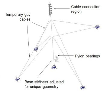
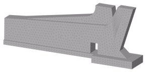 Because
of the unique geometry of the pylon base a separate 3D solid model was
used to fine-tune the base stiffness and beam modelling method used
for the main bridge model. For the main model, section properties for
the pylon itself were obtained from a 3D CAD model. During its construction
the pylon was temporarily restrained using four guy cables at two
vertical levels and in addition to providing support during
construction this also helped maintain alignment and restrict movement
of the pylon prior to the installation of the stay cables and
subsequent post-tensioning of the pylon. Temporary guys, cable load
eccentricities, post-tensioning and time-dependent effects such as
creep and shrinkage to CEB-FIP 1990 were all included and assessed at relevant
stages of the modelling process.
Because
of the unique geometry of the pylon base a separate 3D solid model was
used to fine-tune the base stiffness and beam modelling method used
for the main bridge model. For the main model, section properties for
the pylon itself were obtained from a 3D CAD model. During its construction
the pylon was temporarily restrained using four guy cables at two
vertical levels and in addition to providing support during
construction this also helped maintain alignment and restrict movement
of the pylon prior to the installation of the stay cables and
subsequent post-tensioning of the pylon. Temporary guys, cable load
eccentricities, post-tensioning and time-dependent effects such as
creep and shrinkage to CEB-FIP 1990 were all included and assessed at relevant
stages of the modelling process.