LUSAS Bridge has an
easy to use, associative Modeller for modelling / results processing
and a fully integrated Solver that can also be used independently.
Modelling features
The
LUSAS user interface is a full native Windows implementation providing
an Open Interface to ActiveX compliant Windows software such as
Excel, Access, Word and other software.
Customisation of
menus, toolbars and dialogs plus the ability to create your own
wizards with Visual Basic Scripting provides limitless potential
to tailor the software to specific needs.
Models are formed of
layers where the visibility and properties of each layer can be
controlled and accessed via the layer name held in a Layer
treeview, one of a number of treeviews used to organise and access
model data.
Models
are created using feature-based geometry methods (points, lines, surfaces
and volumes). CAD import / export is
supported. As the model is built up, model features may be grouped
together and manipulated to speed up data preparation or to enable
parts of the model to be temporarily hidden.
A
model merge facility allows design teams to create separate models
of specific parts of a structure and then combine them at a later
date into one master model.
Model attributes
such as thickness, material, loading, mesh/element type etc. can be named explicitly.
Once defined they appear in an attributes treeview ready to be
assigned to selected geometry of the model using the "drag
and drop" technique.
Automatic meshing
is provided with an easy-to-use mesh refinement capability.
Built-in
associativity, a key feature of the LUSAS Modeller, ensures that
if the model geometry is amended, all assigned loadings, supports,
assigned mesh and other attributes are automatically updated to
suit.
Fleshing
(the visualisation of assigned thicknesses or section shapes)
helps to ensure that the thicknesses and eccentricities of slabs
and the orientation of beam members are correctly defined.
Datatips reveal
useful model information such as assigned properties when the
cursor is positioned on top of a geometry feature.
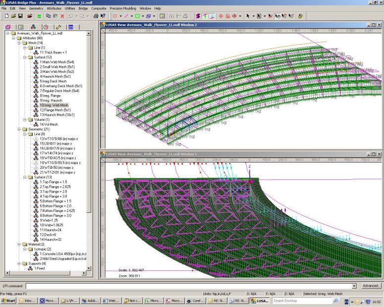
The OpenGL
implementation provides fast graphical displays. Multiple
graphical windows allow simultaneous displays of different parts
of the model at different orientations. Powerful cursor selection
options and pan, zoom, dynamic rotation and pre-defined views
allow for easy viewing and editing of your model.
A multi-level
undo/redo facility allows quick modelling corrections to be made.
Basic geometry data from third-party
BIM/BrIM files (*.ifc) can be imported to create a feature-based
geometry model in LUSAS. Both BIM/BrIM Structural domain files (*.ifc)
and BIM/BrIM Architectural domain files (*.ifc) are supported for
export.
Detailed on-line
dialog help links to additional reference manual material to
provide you with the most appropriate level of assistance at all
times.
LUSAS wizards allow for
quick and easy modelling,
generation of loading conditions, and
viewing of results.
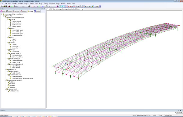
Steel
Composite Bridge Wizard
Use the
Steel Composite Bridge Wizard for
quick and
easy generation of the model geometry and
corresponding mesh, geometric, material, support and local
coordinate attributes for slab-on-beam composite
I-girder bridges. Define models that accommodate:
Straight or curved decks
of constant radius.
An arbitrary skew, where
a skew can additionally be set per support and interpolated
across the spans.
Any number of spans and
supports.
Square and skew bracing.
Transverse stiffeners.
Design utilities for
design checking against supported design code
Use
the wizard to:
Define girder sections
Define cross-sectional
information for a composite girder and slab (without upstands) for all
required locations on the structure.
Visualise the section
being built in real-time as slab, top flange, web, and bottom flange
dimensional data is entered.
Once defined, the
composite I-Girder sections are used to define Girders.
Define girders
Define positions
along the nominal bridge centreline at which pre-defined or
newly created slab and girder cross-sections apply for a girder.
The length(s)
over which section assignments are made for girders either side
of the control centreline is calculated by the bridge
wizard.
Once defined, the
girder components are used to define spans.
Define spans
Define the
girders present in each span along with any bracing runs that
occur between girders. Girders with offset slabs may be mirrored
to create symmetrical arrangements.
Once defined,
spans are used to define a bridge model as a whole.
Define supports
Define supports
for the girders that are present in each span along with any
bracing that occurs between girders at these supports.
Skew can be
defined uniquely for each support, and independently at that
support for any defined support bracing.
Once
defined, the supports are used in the definition of the bridge
model as a whole.
Define whole bridge
Define the type
of bridge (straight or curved) to be generated along with a
minimum mesh size.
Spans defining
the bridge are selected (or defined) along with stating a length
over which they apply. An option to reverse a span is also
provided. Supports at the end of each span also need to be
stated.
Once defined, the
model can be automatically generated by the wizard.
Additional
information relating to transverse stiffeners, bracing assemblies and
intermediate bracing runs may also be specified either during the use
of the wizard, or afterwards to update the initially created model.
Watch how to use the
composite deck wizard
Grillage
wizard
Rapidly
generate a wide variety of orthogonal, skewed and
curved multi-span grillage arrangements. Cracked sections can also
be included.
Watch how to
model grillages using the grillage wizard
Other wizards
Other wizards include those for the calculation
of critical road and rail loading configurations, design
combinations, and dynamic pedestrian loading, along
with loadcase generators for moving vehicle and train loads across
a model.
Animation, graphing and print
results wizards take users through the processes required to
display results.
Section
libraries and section property calculators
Section
libraries and a range of section property calculators help to provide
for straightforward modelling of grid/grillage and beam models.
Standard
Steel Section Libraries
Access
a range of steel sections from libraries including those for:
United
Kingdom
United
States of America
European
Union
Korea
Australia
Canada
China
New
Zealand
India
Precast Beam Section Generators
Use
the precast beam section
generator to calculate section properties of a range of country-specific precast concrete beams including:
United Kingdom Y, YE, TY, TYE, SY, M, UM, and U beam
types
US AASHTO
Type II to VI beams, Florida Bulb T beams
Canadian NU Girders.
An option for including the contribution from a slab is
provided so that the section properties required in a grillage model
can be obtained.
Bridge deck
grillage attributes
Define Bridge Deck
(Grillage) geometric attributes that define geometric properties of
specific types of bridge decks for analysing with reference to, or
derived from grillage formulae published by Hambly and others.
When assigned
to a model along with a Bridge Deck (Grillage) material attribute,
which contains separate material definitions for the slab, girders,
slab and reinforcement (for cracked sections), the different phases of
construction of these types of bridge decks can be analysed using a
single model by the use of the multiple analysis facility.
Standard
section property calculators
Calcuate
section properties for common section
shapes such as rectangular, circular, I-shape, T-shape, L-shape,
T-Shape and Z-shape sections.
Riveted and
welded sections
These include: riveted
I-section, T-shape, box, trough and cruciform sections, riveted boxes
from I sections / channels, I-section with channel, or doubler plates,
and welded plate boxes.
Arbitrary section property
calculator
Use the arbitrary
section property calculator to calculate section property data for any
drawn shape or collection of section shapes.
For thin box sections, only the
points and lines that define the centrelines of the plated
members, and the geometric thickness of each line need to be
initially defined for section property calculation to take
place.
Compound
section property calculator
Define compound sections from
existing library sections. These can be positioned relative to each
other and can have differing material properties assigned.
Infilled/
Encased Sections
Calculate
section property data for the following infill/encased section types:
Filled
box
Filled
stiffened box
Filled
pipe
Filled
stiffened pipe
Encased
hollow box- with rectangular or circular encasement
Encased
filled box- with rectangular or circular encasement
Encased
hollow pipe- with rectangular or circular encasement
Encased
filled pipe - with rectangular or circular encasement
Encased
I-beam - with rectangular or circular encasement
Encased
Cross I-beam - with rectangular or circular encasement
Encased
Combined-T-beam - with rectangular or circular encasement
Arbitrary section property
calculator
Calculate section property data for any
drawn shape or collection of section shapes.
Single and
Multi-Cell Pre-cast Box Section Property Calculator
Calculate section properties of a single or multiple box cross section
(with and without voids) from user defined dimensional data. The section shapes can be defined either as a simple cross-section or as complex section created from as many lines as are required to form a suitable representation of the true cross-sectional shape.
Single
simple box section with void
Multiple
complex box section with void
Tapering beams and multiple
varying sections
Define tapering beams by specifying section properties for each end.
Define multiple
varying sections along a path of lines to easily build models of
bridges having curved soffits, or arch structures having varying
cross-sectional thicknesses.
Definition
of a linear tapering beam
Definition
of a multiple varying section
Use
of the tapering beam and multiple varying section facilities enables
simple prototype and detailed staged construction models of bridges
formed of tapered box sections to be created in a very straightforward
manner.
Preliminary
prepartion of a staged
construction model
Library browser
Use the library browser
to transfer attribute data, such as mesh, geometric, material, etc., between
models.
LUSAS is a trademark and
trading name of Finite Element Analysis Ltd. Copyright 1982 - 2022. Last
modified: March 09, 2023
. Privacy
policy.
Any modelling, design and analysis capabilities described are
dependent upon the LUSAS software product, version and option in use.