Additional Information
See the adjacent Software Information
links for general details regarding LUSAS Bridge software products and
options.
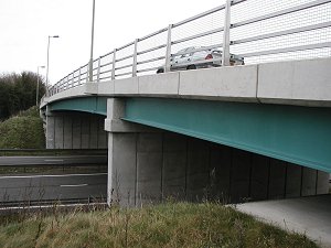
Integral or Jointless Bridges

Integral or jointless bridges are well known to
eliminate the maintenance and salt corrosion problems associated
with bridges having movement joints and bearings. However, the
biggest uncertainty with the design of these types of structures
is the reaction of the soil behind the abutments and adjacent to
the foundation piles caused by seasonal thermal expansion of the
various bridge components acting together. LUSAS Bridge,
unlike some systems, allows you to accurately analyse the
soil-structure interaction of the piles and bridge structure in
one model and comprehensive results processing features give you with
all the tools you need to view and interpret your results.
Overview
 Integral bridges,
or jointless bridges (as they are more commonly known in
the USA) are constructed without any movement joints between
spans or between spans and abutments. Typically these bridges
have stub-type abutments supported on piles and a continuous
bridge deck from one embankment to the other. Foundations are
usually designed to be small and flexible to facilitate
horizontal movement or rocking of the support. Integral bridges,
or jointless bridges (as they are more commonly known in
the USA) are constructed without any movement joints between
spans or between spans and abutments. Typically these bridges
have stub-type abutments supported on piles and a continuous
bridge deck from one embankment to the other. Foundations are
usually designed to be small and flexible to facilitate
horizontal movement or rocking of the support.
With integral
bridges thermal deck movements are accommodated by soil
structure interaction between the supporting piles and the
surrounding strata. Deck loading is also affected by the soil
which acts as both load and support system to the piles upon
which the structures are founded. Specifying a series of spring
supports along a pile to approximate soil behaviour is a
commonly used modelling method when the structural load effects
are the main item of interest. When the soil movement is of
interest continuum models are used instead.
Integral bridges
present a challenge for load distribution calculations because
the bridge deck, piers, abutments, embankments and soil must all
be considered as a single compliant system.
Integral
Bridge Types
There are two main types of
integral abutment bridge:
- Those with short stub-type
abutments that sit on piles and support the deck beams or
slab.
- Those with full abutment
walls, sitting on piles, that retain the ground behind the
wall as well as support the deck beams or bridge slab.
Whilst some analysis systems require
you to use a pile design package to analyse the soil-structure
interaction of the piles before passing results to and from the
structural analysis design package, LUSAS Bridge handles it all
within one analysis system - greatly simplifying your modelling and
analysis.
Modelling and analysis with LUSAS Bridge
With LUSAS Bridge you can model
and analyse
integral abutment bridges in a number of ways:
- 2D beam model with Winkler springs to
represent the horizontal soil continuum.
- 2D continuum model (plane strain) with
staged construction and nonlinear materials for drained and
undrained soil conditions.
- 3D beam analysis with Winkler springs
to represent the horizontal soil continuum.
- 3D shell and beam analysis with
Winkler springs representing the horizontal soil continuum.
- 3D shell analysis with 3D (volume)
continuum to represent the soil.
- Full 3D analysis.
|
|
|
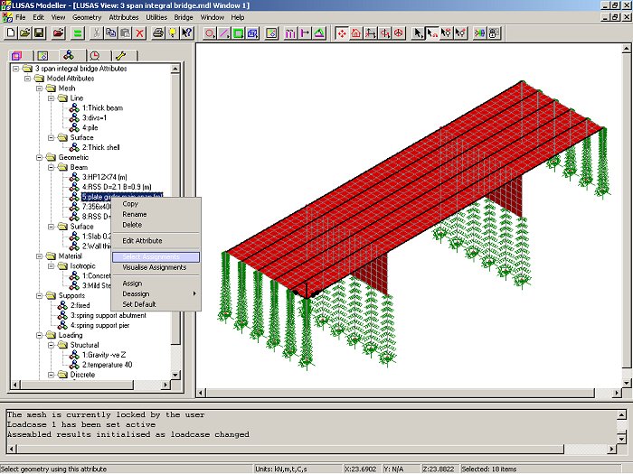
Integral
abutment bridge model using 3D shells and beams with spring
supports representing the horizontal soil continuum. |
Viewing of
results
The following
results are from an analysis of a 3-span integral composite
bridge comprising a concrete deck on steel girders with
concrete diaphragms and abutments supported on H-piles.
Additional
information
 In the UK, the Highways Agency Departmental
Standard, BD57, "Design for Durability", requires
designers to consider designing all bridges with lengths of up
to 60 metres and skew angles of less than 30 degrees as integral
bridges. This advice is intended to prevent problems of joint
leakage over supports and reinforcement corrosion that typically
occur in non-integral forms of bridge construction.
In the UK, the Highways Agency Departmental
Standard, BD57, "Design for Durability", requires
designers to consider designing all bridges with lengths of up
to 60 metres and skew angles of less than 30 degrees as integral
bridges. This advice is intended to prevent problems of joint
leakage over supports and reinforcement corrosion that typically
occur in non-integral forms of bridge construction.
 In the USA, integral abutment bridges have been built since the
1960s and are increasingly being used for replacement
structures. Lengths of integral abutment bridges are also
increasing and now the state of Tennessee builds steel
superstructure bridges up to 400 ft. (122m) long with no joints;
and concrete superstructure bridges of this type up to 800 ft.
(244m) and sometimes longer. One case in point is the bridge
carrying Route 50 over Happy Hollow Creek - at a total length of
1,175 ft. (358 m), it is the longest, jointless, integral
abutment bridge in the country.
In the USA, integral abutment bridges have been built since the
1960s and are increasingly being used for replacement
structures. Lengths of integral abutment bridges are also
increasing and now the state of Tennessee builds steel
superstructure bridges up to 400 ft. (122m) long with no joints;
and concrete superstructure bridges of this type up to 800 ft.
(244m) and sometimes longer. One case in point is the bridge
carrying Route 50 over Happy Hollow Creek - at a total length of
1,175 ft. (358 m), it is the longest, jointless, integral
abutment bridge in the country.
Paper
and Presentation: Integral Bridges and the Modeling of Soil-Structure
Interaction
-
Paper presented at IBC
2014 by Steve Rhodes and Terry Cakebread of LUSAS.
-
At the time of writing
the paper, no standard approach for the analysis of integral
bridges appears in AASHTO LRFD Bridge Design Specifications or
other international codes. This paper considers the approaches
most suitable for modeling common integral bridge forms, expanding
upon recent guidance regarding soil-structure interaction
approaches. Issues including material properties, initial stress
state and the incorporation of the effects of soil ratcheting are
discussed and both continuum and spring-type finite element models
are explored.
-
View
paper | View
presentation
Share this
article
|