|
||||||||||||
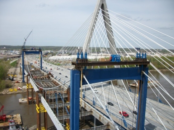
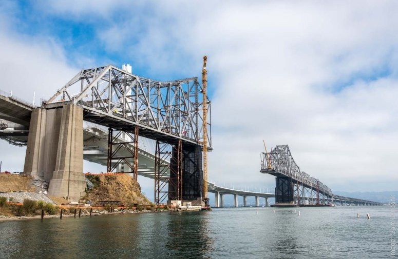
Layout and primary dimensions of the old East Main Span. Bridge construction The old East Main Span was a steel cantilever truss bridge consisting of built-up truss and bracing members composed of plates and rolled sections. The chords and larger diagonals were box-shaped with solid plates on all 4 sides. Lighter members were latticed with lacing angles and/or bars. Eyebars were used for chords and primary diagonals with large tension loads. The main span was approximately 2,416� (736m) long with a clear span of 1,400� (428m) between the two primary bridge piers. The bridge had two decks. In the original configuration, the upper deck carried automobile traffic in both directions, and the lower deck carried trains and truck traffic. In the 1960s the bridge deck was retrofitted to remove train traffic from the bridge. After the retrofit the upper deck carried all westbound traffic (to San Francisco), and the lower deck carried all eastbound traffic (to Oakland). Additional retrofits were completed after the 1989 Loma Prieta earthquake to repair damage caused by the earthquake and to improve future seismic performance. In the years following the earthquake it was determined that it would be cost prohibitive to retrofit the bridge to comply with all modern seismic design requirements, and this contributed to the decision to construct a new bridge and dismantle the original east span.
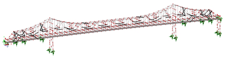
A single LUSAS model was used to simulate the entire dismantling sequence for the old East Main Span. Modelling in LUSAS Before any bridge dismantling procedures could be modelled, a single global model representing the current in-service configuration needed to be created using accurate member cross-sections and weights. A thorough review of the 1930s era as-built fabrication drawings, which were provided by Caltrans, provided section properties, member weights, and deck weights. The original design drawings that were available included stress sheets that provided the original designer�s member forces as well as pier reactions. This information allowed the LUSAS model to be "benchmarked" against the original design and ensured that bridge member forces and reactions could be reliably predicted. After the model was benchmarked, it was updated with the various retrofits that had been carried out. This included modifying the deck weight and updating the floor system. At first glance, it appeared that the erection sequence would not have much bearing on the output of the model. However, as the erection sequence was studied in greater detail, it was found that during several stages of construction the bridge was jacked at various locations to allow for correct fit-up of members and to ensure that the deformed shape of the bridge was correct. This jacking resulted in locked-in erection forces that needed to be considered in the model. Modelling this erection sequence was critical in the development of an accurate model.
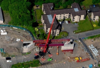
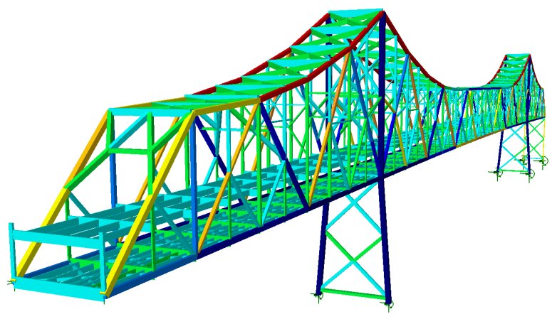
In-service axial forces prior to dismantling being carried out Bridge dismantling The proposed dismantling sequence approximately reversed the sequence used to construct the bridge. Caltrans made available a detailed description of bridge erection procedures so that the subtleties of the bridge erection could be modelled and accounted for in the dismantling procedure. All dismantling was generally carried out using hydraulic cranes and excavators located on the bridge lower deck. Each dismantling stage in the model considered the positioning of the equipment and removal of truss members. Key aspects of the dismantling sequence for which LUSAS was particularly useful were:
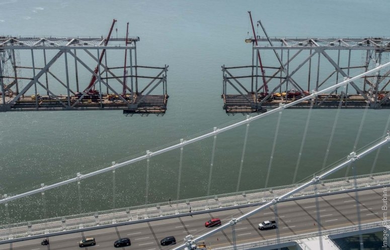
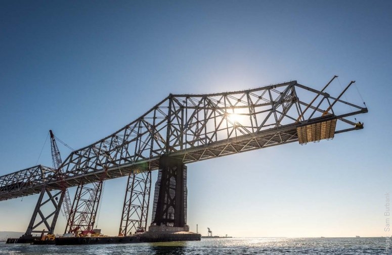
In-service axial forces prior to dismantling being carried out, with the suspended span easily identifiable. Making "The cut" at midspan The bridge was constructed with the two halves of the cantilever extending to midspan, the opposing halves cantilevering 700 ft (214m) from each of the main piers. Jacks on the upper chord and lower chord adjusted the position of the bridge so that the two halves could be aligned and connected. After the bridge was connected at midspan, the suspended span was "swung" by releasing the upper chord at both ends of the suspended span, allowing the bridge to relax into its designed configuration. The swinging resulted in the 576 ft (176m) suspended span simply hanging from the tips of the opposing cantilever arms. The contractor opted to remove the cantilevered structure by substantially reversing the original engineered erection sequence. To accomplish this, the main span needed first to be converted from its relaxed "swung" configuration into two independent cantilevers, then severed at midspan prior to proceeding with the dismantling of the opposing halves. This procedure of severing the main span became known to the engineers as "The cut". Nathan Miller, Bridge Engineer at Foothills Bridge Co. explains: "Before this could be done, the upper chord at each end of the suspended span needed to be re-engaged to convert the suspended span into extensions of the cantilever, and then be jacked to relieve the forces in the suspended span. This would then allow the bridge to be cut at midspan without a large release of energy and minimal bridge deflections. By using LUSAS to model this sequence we could provide the contractor with the required jacking forces and expected bridge displacements." At each end of the suspended span, the upper chord was jacked to approximately 2,000,000 lbs (8900kN) of force per truss, equating to a displacement of approximately 5" (125mm). Additionally, the lower chord was jacked with 250,000 lbs (1100kN) force in each truss to relieve a small remaining tension in the lower chord prior to cutting. Bridge jacking was modelled in LUSAS by applying the jacking force and then activating the relevant bridge member in the model in order hold the force (and displacement). The observed bridge displacements during upper chord jacking agreed favourably to those predicted by the LUSAS model, and provided the contractor with a high level of confidence in carrying out "The cut".
Initial dismantling following "The cut" at midspan.
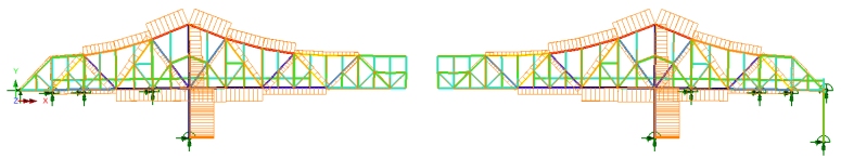
Axial forces in truss members after initial dismantling at midspan. Temporary Truss Members and Local Tension Release After the two halves of the bridge were separated numerous stages in the dismantling process had to be considered. A series of loadcases were defined in LUSAS to account for various equipment arrangements on the bridge, the removal (the deactivation in the model) of truss members and the installation (the activation in the model) of temporary truss members and support towers. The modelling sequence performed in LUSAS allowed the engineers to identify critical dismantling stages when primary load path members needed to be removed and temporary members needed to be installed. Several demolition stages involved the removal of primary truss members with significant residual tension. To prevent sudden, uncontrolled force transfer between existing and new temporary members, local tension release devices were employed, using design forces and displacements provided by the LUSAS model.
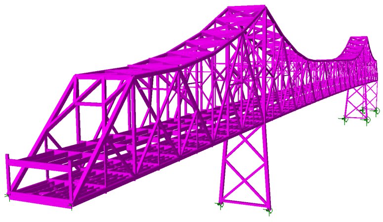
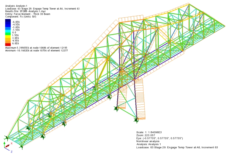
Location of temporary truss members and additional bracing members required for particular stages of dismantling. Anchor Span Temporary Towers and Temporary Truss Members The upper chord in the anchor arms (and cantilever arms) was composed of eyebars, which were under significant tension in the bridge�s in-service condition. However, as the bridge was dismantled back from midspan, the weight in the cantilever was reduced, and consequently the eyebar tension also reduced. This meant that at some point, the weight of the anchor span relative to the weight of the cantilever would become critical and the tension in the eyebars would be eliminated. Since the eyebars were very slender and had essentially no compressive capacity, this would have created an unstable structure. So, in order to prevent the premature detensioning of the anchor span eyebars, temporary support towers in the anchor span were used to support/lift the anchor span, inducing more tension in the anchor span eyebars. LUSAS was used to monitor the eyebar tension in the anchor span and highlighted when temporary support towers were required for a particular dismantling stage. The temporary tower jacking/installation was modelled in LUSAS by applying the jacking force at the required node, activating the tower support, and then removing the jacking force. After the temporary towers were installed, the truss was jacked into a favourable position to balance the critical variables of the eyebar force, temporary truss member design forces, and pier reactions. As dismantling of the truss approached the main piers, the temporary towers alone would not be adequate to maintain tension in the anchor span eyebars, so in order to maintain the stability of the structure, temporary members were installed to create an alternate load path. After the installation of the anchor span temporary truss members, the anchor span eyebars were no longer required and could be removed or allowed to buckle.
Location of temporary towers and temporary truss members
Dismantling progressing Typical LUSAS results obtained
Animation of axial forces during erection, in-service alterations, and dismantling.
Animation of axial forces in members during dismantling
Detail of axial force results for western anchor span In summary Foothills Bridge Co. used a single LUSAS model to model the entire dismantling sequence of the East Main Span of the San Francisco-Oakland Bay Bridge. The model incorporated equipment and environmental loads (in addition to dead load), and determined existing truss member forces, temporary truss member design forces, temporary tower loads, and temporary tower jacking forces. Forces and bridge displacements were monitored by the contractor the throughout the dismantling sequence and these field measurements were found to be in compliance with those predicted by the LUSAS model, verifying the bridge was behaving as expected, and providing confidence to all during the dismantling process.
"By identifying and analyzing the critical steps in the planned dismantling sequence, LUSAS proved to be an invaluable tool in helping us to evaluate bridge stability and predict dismantling effects on a very large and complex structure." Nathan Miller, Bridge Engineer, Foothills Bridge Co.
Animation of bridge dismantling from September 2014 to April 2015 (based on images courtesy of Caltrans) Unless otherwise noted, all photographic images are courtesy of Sam Burbank.
Share this article
Find out more
Other LUSAS Bridge case studies:
|
|
Software Information
|
||||||||||
|
 Find
out more:
Find
out more: