 Case
Study Case
Study
DART Blue Line Extension
-
Design of bridges on a 4.75 mile light rail extension
-
Rail
track-structure interaction analysis of two multi-span precast
concrete beam structures
-
Detailed
modelling and analysis of a steel through girder span
As
part of a design-build team, Gannett Fleming Engineers and Architects
P.C. provided design services
for Dallas Area Rapid Transit's (DART) Blue Line Light Rail Transit
Expansion which runs from the downtown Garland Station to the city of Rowlett,
Texas. In addition to the systems design, including track work, and overhead catenary
systems, Gannett Fleming was
also responsible for the design of a number of new bridge structures along
the route and used LUSAS Bridge
analysis and Rail track analysis software to assist with its design of
the two longest structures.
Overview
The Dallas Area Rapid Transit (DART)
light rail system is the largest electric light rail system in the
United States. It currently totals 85 miles (137 km) of track and 61
stations between its Red, Blue, Green and Orange Lines, with plans in
place to further increase its size. The 4.75 mile (8km), $360 million,
twin track extension to the Blue Line opened to the public in December
2012. Its construction required six new bridge structures to be
designed, the longest of which is a 28 span, pre-cast concrete beam
structure over Rowlett Creek. This and an 11 span bridge carrying the
extension over the Kansas City Southern (KCS) Railway were both
analysed using customized LUSAS Rail Track Analysis software to assess
track-structure interaction effects and verify that key values were
within acceptable limits.
|
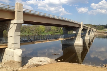
Rowlett Creek Bridge
Rowlett Creek bridge is a 2,565 foot (782m) long
structure
that takes the DART Blue Line extension over Rowlett Creek.
Its
deck spans are formed
from AASHTO Type IV prestressed beams that vary in number
according to span length with six beams used on the two 105'-0"
(32m) spans and four beams used throughout the remaining 91'-0"
or 92'-0" (28m) spans. The beams are supported on a flared pierhead
sitting on a single, 6'-0" (2m) diameter reinforced concrete column
with 2" (50mm) expansion joints
between each span. Direct-fixation
fasteners restrain the track to the concrete
plinths that run the length of each 33'-2" (10m) wide reinforced
concrete deck.
Track-structure
interaction analysis
By using LUSAS Rail Track Analysis software
the track-structure interaction model was built automatically from geometric,
material property, and loading data defined on separate worksheets in a MS Excel spreadsheet.
Thermal loading to the track and train loading due to
acceleration and braking forces could be defined, and rail clips, bearings and pier stiffnesses
could all be included in the
analysis model. Model building dialogs allowed for modelling either one train
crossing, or for multiple trains crossing the structure. Deck temperature loading
could be considered in isolation for subsequent analysis of multiple rail
configurations, or a full analysis could be carried out considering the
combined temperature in the deck and rail loading. Because the
response of the track fixing clips is always nonlinear, a
nonlinear analysis was required.
|
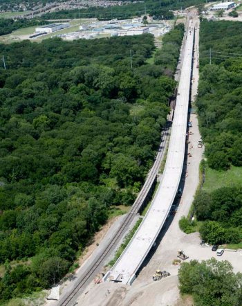
Rowlett Creek
Bridge during construction |
|
After running
a track-structure interaction
analysis, results can be produced in either Excel spreadsheet along
with automatically created graphs, or in standard LUSAS results
file format. Enveloping of results is carried out automatically
inside Excel, or by specifying user-defined load combinations
inside LUSAS. With Excel,
separate worksheets within the results spreadsheet contain
results for specific areas of interest. These worksheets
include:
-
Raw
results data in summary, graph and tabular form for each
track and deck component
-
Envelopes
of raw track and deck data in summary, graph and tabular
form for combinations of temperature and trainset rail
loading
- Tables of railbed
displacements, longitudinal reactions, and rail stress
values - providing key results in summary form and allowing
the quick determination of which analysis is causing the
worst effects for each of the checks that need to be carried
out.
Structural
elements such as the track, decks, bearings, piers and
foundations are stored as individual groups within LUSAS and
this allow for easy selection by structural type when viewing
displacements, stresses or reactions etc. If
additional spot checks need to be performed at specific
locations on the tracks, the areas of interest can be selected
and analysed automatically.
The use of
track-structure interaction software has many benefits over
manual methods: Automated model building guarantees
correctly-built models compared to manual model creation; the
material properties associated with the track/structure
interface are automatically updated according to the position of
the passing train or trains; and overall it provides a much
faster assessment of thermal and / or train loading track
interaction effects on multi-span structures.
Eric
Dues, Principal Engineer at Gannett Fleming said: "An
independent verification of the thermal interaction results obtained
using LUSAS for the Rowlett Creek bridge was carried out by engineers
in another Gannett Fleming office using different software. The
results were strikingly similar, verified the LUSAS modelling method,
and illustrated just how efficient LUSAS is at modelling
track-structure interaction effects for these types of bridges."
|
|
|
|
Rowlett Creek
Bridge
|
|
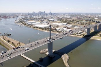
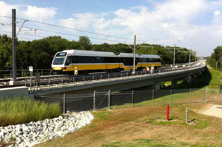
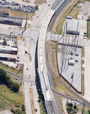
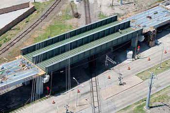
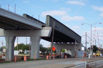
KCS/N.
First Street Bridge
KCS/N.
First Street Bridge is
a
1,054 foot (321m)
long structure that carries
the two DART light rail tracks over the KCS Railroad and North First
Street in Garland. Its
deck spans
are formed from AASHTO Type IV prestressed beams that typically span
85-90 feet (26-27.5m)
between crossbeams supported by a pair of rectangular
reinforced concrete columns.
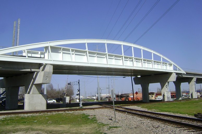
Its
155 foot (47m)
long second
span is a welded through girder structure comprising two welded plate
exterior girders with 3" x 30" (762mm) top and bottom
flanges and 1"x105" (2.67m) webs and a single interior
welded plate girder with 3"x30" (762mm) top and bottom
flanges and 1"x126" (3.2m) web. The girders are braced
with W14x14 floor beams that also support the 8" (203mm) thick reinforced concrete deck slab.
As
for the Rowlett Creek Bridge, direct-fixation
fasteners are used to restrain the track to the
concrete plinths running the
length of the deck. An
aesthetic non-structural arch is affixed to each outer girder.
As well as carrying out a track-structure
interaction analysis for the whole structure, various detailed beam
and shell element models of the second span
were built in LUSAS to
assess different span solutions.
Particular
attention was made to the modelling of the crossbeam/girder
connections to
determine dead and live load stresses for use in the design which was to
the AASHTO standard specification, as modified by the DART Design
Criteria Manual.
Moving train load cases were enveloped and combined with dead loads to
determine maximum in-service effects. In addition to
the determination of the stresses, eigenvalue analysis with LUSAS
helped determine the natural frequencies of the structure.
|
KCS/N.
First Street Bridge
during construction
|
Illustrative
model and results plots
|
|
|
LUSAS rail
track-structure interaction model for KCS/N First Street Bridge |
|
|
|
|
|
LUSAS modelling of steel
through girder span |
|
|
|
|
|
Stresses in
girders, deck and floor beams for a particular train loading position |
|
|
|
|
|
| Through
girder span during construction |
KCS/N.
First Street Bridge
during construction |
| |
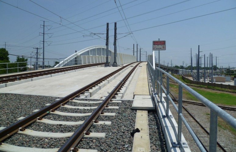 |
| KCS/N
First Street Bridge on completion |
"An
independent verification of the thermal interaction results obtained
using LUSAS for the Rowlett Creek bridge was carried out by engineers
in another Gannett Fleming office using different software. The
results were strikingly similar, verified the LUSAS modelling method,
and illustrated just how efficient LUSAS is at modelling
track-structure interaction effects for these types of bridges."
Eric
Dues, Principal Engineer, Gannett Fleming Engineers and Architects,
P.C.
Find out more
Other LUSAS Bridge case studies:
|
|
Software Information
|