 Case Study Case Study
Share this
article
Rail track / structure interaction
analysis for the Dubai Metro light rail project
-
2D modelling of
rail / structure interaction modelling to UIC 773-4
-
Verification
of spreadsheet calculations
-
Potentially
problematic results proved by LUSAS to be within project design
criteria
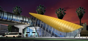
The Red and Green
Lines of the Dubai Metro light rail scheme are being constructed
as a Design-Build contract by a consortium of international
contractors. Atkins,
one of the world�s leading engineering and design
consultancies, is the lead designer to the major civil
contractor of the Dubai Rapid Link (DURL) Consortium and is
carrying out the full multi-disciplinary design and project
management of the civil works for the project. Atkins used LUSAS
Bridge analysis software to verify its rail track interaction
spreadsheet calculations to the International Union of Railways
Code UIC 774-3, and to obtain more accurate and ultimately
design-complying results for situations that the spreadsheet
calculations had identified as exceeding project design values.
|
Overview
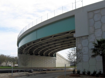
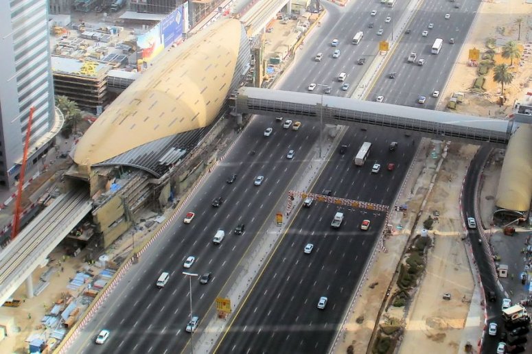
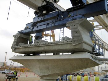
The
52km long Red and 24km long Green Lines of the Dubai Metro run mostly
on elevated single span pre-cast post-tensioned concrete deck units of
U-shaped cross-section. Deck crossbeams sit on elastomeric bearings,
with fixed and free guided sliding pot bearings being used for two and
three-span continuous decks. Standard spans are typically 28m, 32m or
36m in length, with each end supported on a flared pierhead sitting on
a single, circular, reinforced concrete column. Rails are continually
welded across all the decks and deck joints, and connected to concrete
plinths running the length of each deck using regular track fixings.
A detailed assessment of the
interaction of the track with respect to the deck structures was
needed in order to derive stresses in the rails and forces and
longitudinal displacements induced in the deck caused by both thermal
and train loading.
|
|
Spreadsheet calculations
Based upon the formulae and design
methods specified in the UIC 774-3 code Atkins set-up spreadsheets to
calculate rail track/structure interaction effects for around 1200
spans on both the Red and Green Lines. Whilst based on the simplified
techniques of the UIC code and producing generally conservative
results this spreadsheet approach had the benefit of allowing a large
number of span arrangements to be assessed relatively quickly.
|
Modelling with LUSAS
To
verify the results obtained from the spreadsheets Atkins used LUSAS to
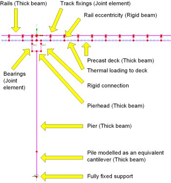
model and analyse a number of representative span arrangements. Models
were built using thick beam elements to represent the piles, piers,
crossbeams and concrete decks. Pile modelling was done using the
equivalent cantilever method (as opposed to modelling the
soil/structure interaction as a beam with elastic springs). Joint
elements of an appropriate stiffness and at the required locations
modelled the elastomeric and other bearing types. A single thick beam
element offset by an appropriate eccentricity from the deck
represented both sets of rails. Nonlinear joint elements modelled the
track fixings. Thermal loadcases were applied to the elements
representing the deck according to the UIC 774-3 code. Train loading
of both vertical live loading and horizontal braking loads were
applied to the elements representing the rails at locations of
interest in the model.
|
|
|
|
|
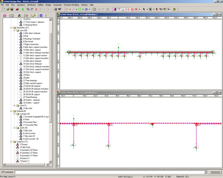
LUSAS modelling of
a multi-span arrangement including a 2-span and 3-span
continuous deck |
Rachel Jones, engineer on the project
said: "For the LUSAS verification modelling we chose a selection
of span arrangements that would give us a variety of effects for a
combination of single, 2-span and 3-span continuous decks. The
stresses in the rails obtained from the LUSAS analyses proved our
spreadsheet calculations were being carried our correctly".
However, for a small number of span arrangements the rail structure
interaction forces obtained from the spreadsheet calculations were
shown to exceed project design values. Each of these situations required
additional LUSAS models to be created for a detailed analysis to be
carried out. The primary difference between analysis to the UIC-773
code and using LUSAS is that modelling in LUSAS is more realistic
(using nonlinear joints to model the track fixings for example) and
makes no assumptions on the behaviour of the structure. Results
obtained from the LUSAS analyses showed that the rail/structure
interaction values of initial concern did not actually exceed the
project design values.
|
|
|
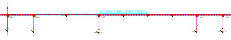
Loading
configuration: temperature loading to deck and vertical live
train loading with braking forces (not visible) in first two
spans of station |
|
|
|
|
|
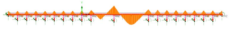
Stress in rails
from applied thermal and train braking loading |
"By using LUSAS to investigate
these span arrangements we got a more accurate assessment of the rail
track interaction effects and obtained values that did not exceed
design criteria"
Rachel Jones, Atkins
| Automated
rail track / structure analysis with LUSAS
If it had been available at the
time Atkins carried out its own manual
2D modelling and analysis of rail track / structure interaction
effects as described in this case study, the LUSAS
Rail Track Analysis software option for LUSAS
Bridge would have let Atkins carry out automated 2D modelling of track/structure
interaction analysis to the International Union of Railways Code
UIC 774-3.
With this option, track and bridge
interaction models are built automatically in LUSAS from
geometric, material property, and loading data defined in a MS
Excel spreadsheet. Both thermal loading to the track and train
loading due to acceleration and braking forces can defined. Rail
clips, ballast movement, bearings and pier stiffnesses are all
included in the analysis model. The model building dialogs allow
for either one train crossing one or more structures, or for
multiple trains crossing the same structure.
When running an analysis, deck
temperature loading can be considered in isolation for
subsequent analysis of multiple rail configurations, or a full
analysis can be carried out considering the combined temperature
in the deck and rail loading. Because the response of the
ballast and/or track fixing clips is nonlinear, a nonlinear analysis always
needs to be carried out. After running an analysis, results can
be quickly obtained in both spreadsheet or LUSAS results file
formats.
A key benefit of using the LUSAS
Rail Track Analysis software option is that it automatically
updates the material properties associated with the
track/structure interface based upon the position of the train
or trains crossing the bridge - something not easily done by
manual or other software methods. |
Other analyses undertaken by Atkins on
the Dubai Metro light rail project using LUSAS include:
Share this
article
Find out more
Other LUSAS Bridge case studies:
|
|
Software Information
|