Case Study
Share this
article
The
Helix Bridge
- Glass and steel retractable
footbridge
- Global modelling of stresses in
glass, adhesive and cantilevered walkway
- Localised modelling of key
individual components
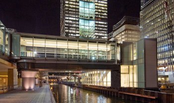
The Helix Bridge at the Paddington
Basin development adjacent to Paddington Station is a retractable,
composite glass and steel pedestrian bridge. It has a helical frame
which rotates during deployment to give the appearance of it
corkscrewing across the canal. Davy
Markham used LUSAS to ensure that the proposed form
of construction would not excessively stress the glass or adhesive
bonds whilst operating under self-weight.
Redevelopment scheme
The Paddington Basin development is one
of the largest urban regeneration projects in Europe. As part of a
masterplan to restore links within the local community, a network of
new footpaths; a towpath along the canal to Little Venice; and several
pedestrian bridges, such as this Helix Bridge, by Marcus Taylor, and
the Rolling Bridge, by Thomas Heatherwick were designed and installed
on behalf of Paddington Development Corporation.
|
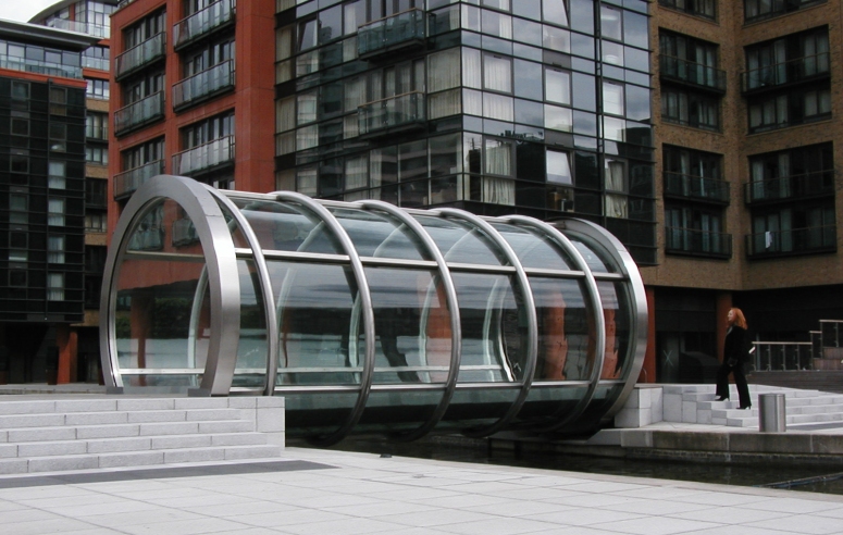
Construction
The glass and stainless steel helix
structure measures 7.2m long x 3.5m in diameter and surrounds a 2m
wide cantilevered, carbon steel walkway which can be retracted to
allow the passage of water traffic. The composite tube is fabricated
from a tubular helix or �corkscrew� formed from 140mm diameter
Circular Hollow Sections to which are bonded a number of curved,
trapezoidal sheets of toughened laminated glass. Welded along the full
length of the helix are six 80mm square-section transoms or cross
members, which provide mounting points for the laminated glass panels.
The 15mm thick glass is bonded to the transoms with structural-grade
glazing adhesive and the joins covered by sealing strips. Analysis
with LUSAS was required to ensure that the proposed form of
construction would not excessively stress the glass or adhesive bonds
whilst operating under self-weight.
|
|
| Modelling
and analysis
A model of the whole structure
allowed global stresses and displacements in the glass and steel
members of the assembly to be obtained and assessed. 3D beam
elements modelled the tubular helix section and the transoms. 3D
shell elements modelled the glass panels, the sealant running
around the "circumferential" joints, and the adhesive
used to fix the glass to the transoms. Elements representing the
adhesive and sealant were easily isolated to enable contour
plots of stresses and strains in these critical regions to be
produced. A broken glass scenario, as well as a wide range of
operating loads and conditions was also considered. |
 |
Localised models
investigated stresses at selected intersections of the Circular Hollow
Section helical members and Square Hollow section transom members. CHS
wall thicknesses were evaluated and an optimum thickness obtained.
Regions of individual transom members that required reinforcing were
also identified.
"Finite
element analysis with LUSAS was essential on this project and proved
that the differential movement between the glass and the steel helix
was within the strain limits of the silicon adhesive."
Phil Snowsil, Senior
Design Engineer, Davy Markham
Share this
article
Find out more
Other LUSAS Bridge case studies:
|