|
|||||||||||||||||||||
Spea Engineering spa used LUSAS Bridge and the Steel and Composite Deck Designer software option to investigate and optimise the design of integral bridges to the Eurocodes. For this, two main span configurations were chosen, characterized by having a one and three-span arrangement respectively, with maximum lengths of the main span equal to 38 and 45.5m depending on the standard width of the overpassed highway carriageway. As a result of the analyses carried out and the design checks made, time-consuming manual checks were avoided and optimised steel beam and reinforcement bar sizes were obtained, saving nearly 25% in structural steel weight over values calculated for a simply supported scheme. Single span bridge The main scheme of the bridge comprises two 1600mm deep longitudinal steel beams that support a 13.5m wide composite concrete deck. Eight equally spaced transverse steel �I� beams provide lower lateral restraint to the main beams. At each end, the longitudinal beams are embedded into a retaining wall that itself rests upon a substantial 1.2m thick retaining wall that is cast onto a pilecap sitting on eight, 1.2m diameter, closely spaced piles. The entire system creates a single frame system that is designed to absorb all forces imposed upon it.
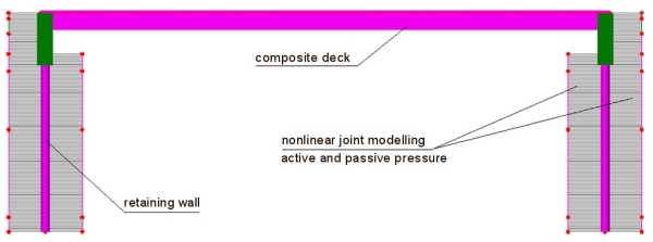
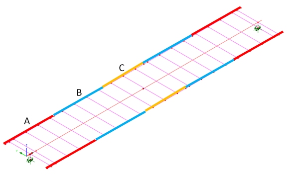
Modelling and analysis Using LUSAS, a single 3D model was created to represent all stages of construction and model the soil-structure interaction that took place. Joint elements accommodating nonlinear behaviour modelled the active and passive soil pressures. The main longitudinal steel beams were divided into five segments labelled A, B, C, B, A (as shown below) to optimize the thicknesses of webs and flanges. Design checks Using moment and shear data generated from the LUSAS analysis, the steel and composite deck designer carried out ULS bending, stress, shear and interaction; and SLS stress, web breathing and fatigue checks for the main structural members and connectors. From the analyses carried out and the design checks made, time-consuming manual checks were avoided. Optimised steel beam flange, web, and reinforcement bar sizes were obtained (see below) for a simply supported and for an integral bridge limiting the maximum utilization factor to 0.95. Overall, a saving of nearly 25% in structural steel weight was obtained for the integral bridge design with respect to the simply supported one, while the reinforcing steel in end regions of the slab needed to be increased due to the hogging bending moments produced by the connection between deck and abutment. Integral abutments can be slender as well, but they need a greater amount of steel reinforcement. From a global point of view, the integral abutment offers a large saving with respect to the traditional abutment of about 30%.
Sensitivity to different structural schemes Different transverse steel arrangements with four longitudinal beams and three-span bridges were also analyzed and the results compared between integral and simply supported bridge types. Results varied slightly but in all case studies analysed the integral bridges appear to save costs and also offer greater quality and durability.
L. Ferretti Torricelli, of the Bridge Design Department at Spea Engineering spa, said: "The use of LUSAS with nonlinear joints modeling the active and passive pressure allowed us to have an integrated model of the deck and the abutments that will be used also for seismic analysis, and the use of the steel and composite deck designer was mandatory to enable us to optimize the design in a reasonable amount of time in accordance with relevant Eurocodes." "The use of LUSAS with nonlinear joints modeling the active and passive pressure allowed us to have an integrated model of the deck and the abutments that will be used also for seismic analysis. The use of the steel and composite deck designer was mandatory to enable us to optimize the design in a reasonable amount of time in accordance with relevant Eurocodes." L. Ferretti Torricelli, Bridge Design Department, Spea Engineering spa Find out more
Other LUSAS Bridge case studies:
|
|
Software Information
|
|||||||||||||||||||
|
|||||||||||||||||||||