|
||||||||||||||||||||||||||
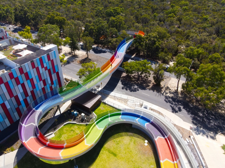
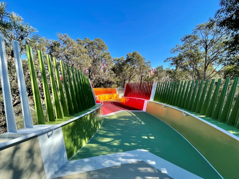
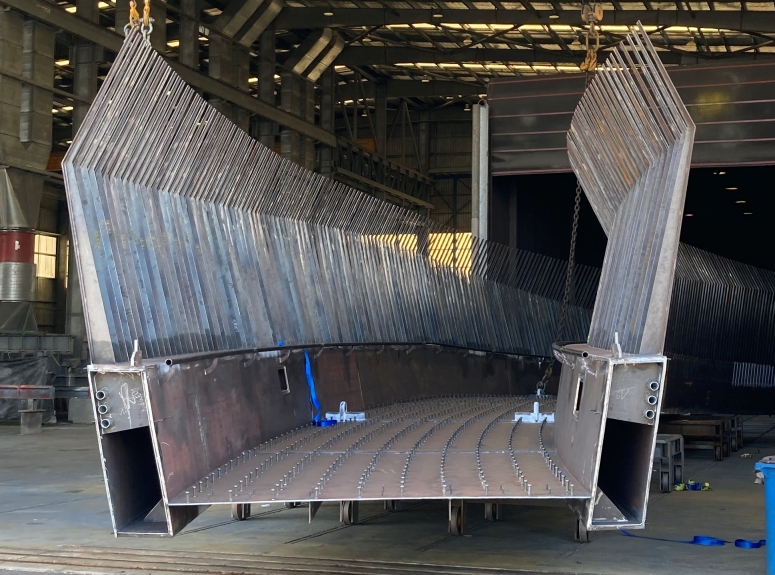
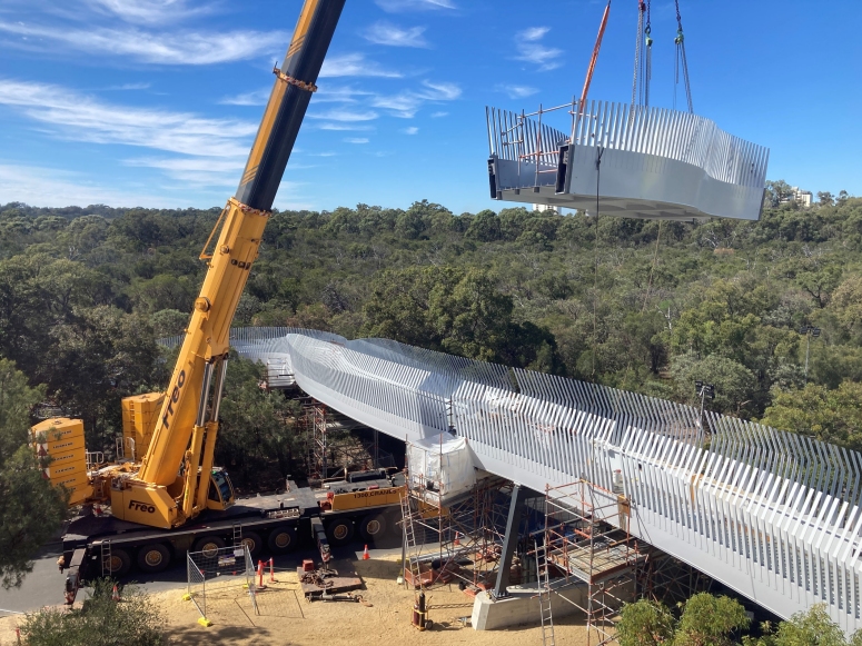
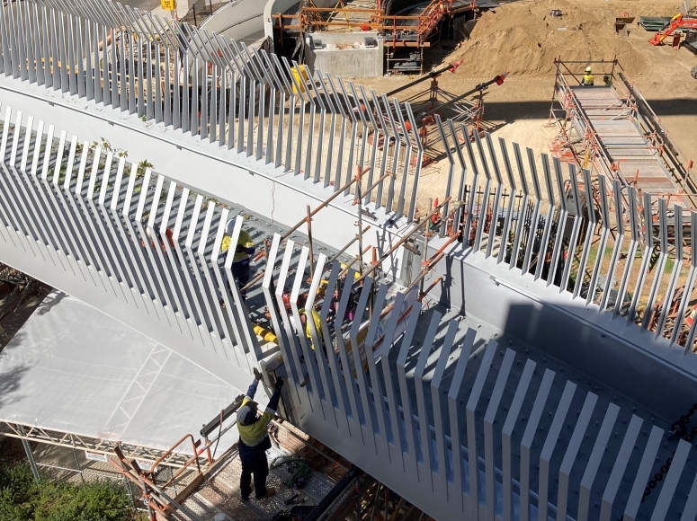
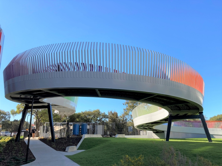
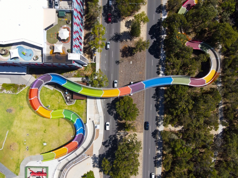
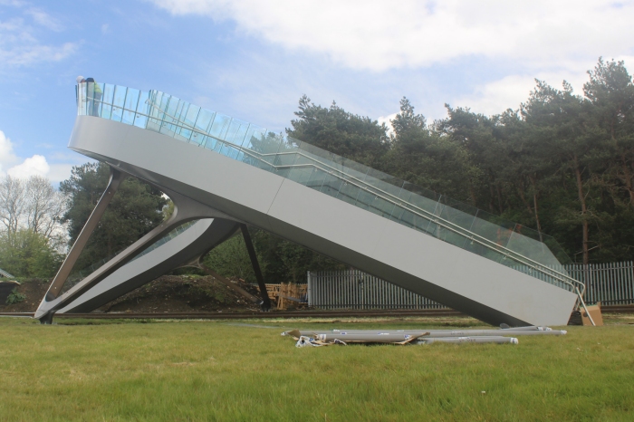
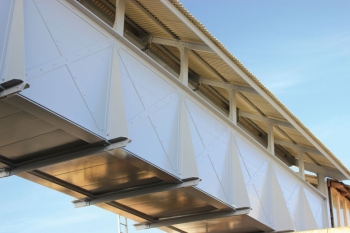
Bridge description The total bridge length of approximately 217m comprises 170m of elevated structure, with approach ramps of 30m and 17m at each end. The elevated structure comprises six continuous spans. The two main spans over Winthrop Avenue are approximately 38 m long, with the remaining approach spans having a maximum span of approximately 29m. The alignment comprises eight distinct horizontal curves in addition to a vertical curve over Winthrop Avenue. The superstructure is a through girder design comprising two 1200mm deep by 400mm wide fabricated steel box girders. The box girders are braced by 250mm deep RHS cross beams and a stiffened steel plate. A 125mm thick concrete deck acts compositely with the stiffened steel plate and box girders. The deck is supported on proprietary pot bearings. A through girder design was selected to reduce the superstructure depth extending below the finished surface, which reduced the overall bridge length and the amount of clearing and disturbance within Kings Park. The piers comprise inverted U-frames constructed from fabricated steel box sections. The column box sections taper from 300mm at the base to 400mm at the top, with the top horizontal member having a constant width. The piers are supported on concrete spread footings, except for the central pier which is supported on piles. The abutments comprise concrete L-shaped retaining walls. The box shape on the bridge continues along the approach ramp retaining walls to provide continuity of form for the full length of the bridge and approaches. The walls are inset from the box section to accentuate this feature.
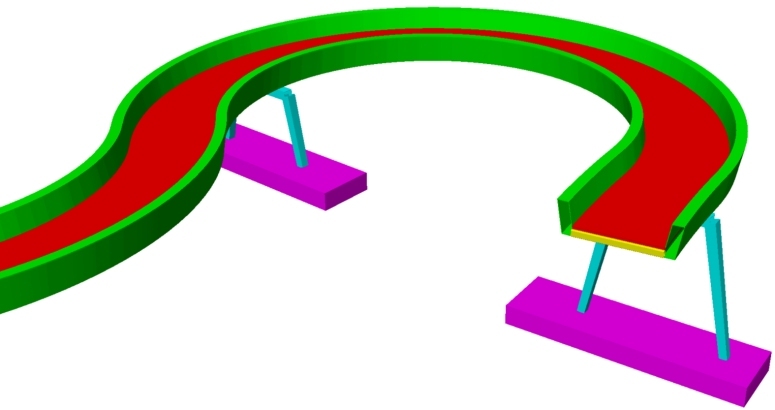
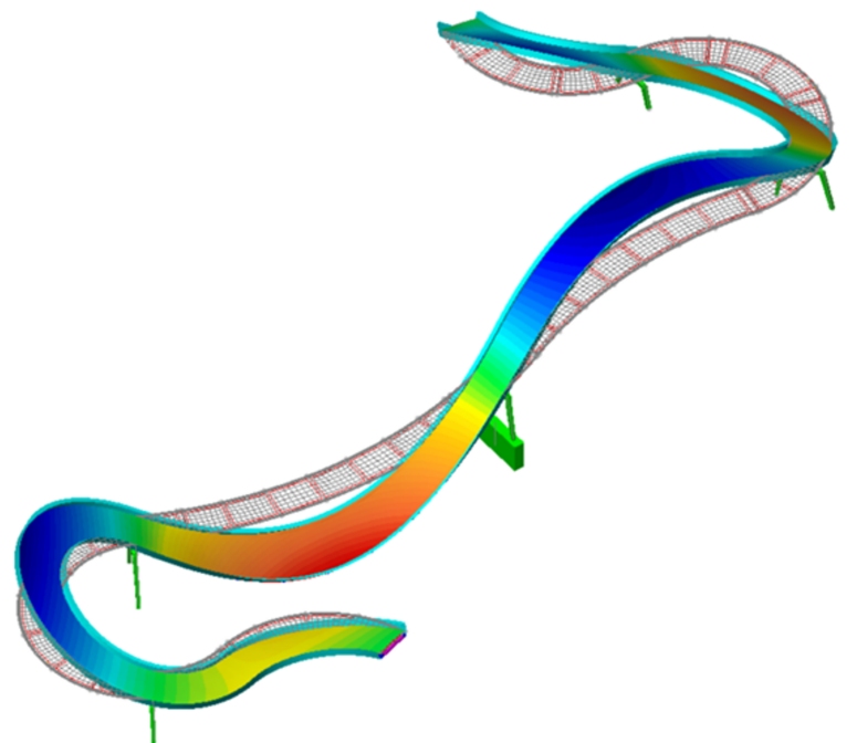
Modelling with LUSAS AECOM used LUSAS Bridge to model the structure and undertake the required dynamic and buckling analyses. Beam elements represented the asymmetric box girders, cross girders, and pier columns, with shell elements used to model the concrete deck, stiffened deck plate and spread footings. Offsets were used to ensure the correct eccentricity of the respective elements. Springs modelled the soil stiffness.
Staged construction modelling An accurate construction stage analysis was required since the girder articulation and stiffness varied throughout the construction stages. The continuous girders were initially erected as simply supported segments on temporary props. Girders segments were then spliced, and the props were subsequently removed. The concrete deck, which acts composite with the girders, was then cast. The analysis also included time-dependent creep and shrinkage of the concrete deck slab. Optimised workflow and member sizes Locating piers was challenging due to the serpentine alignment, and the highly constrained site. The design workflow enabled various span arrangements to be compared quickly. This allowed the design team to balance spans and reduce the number of supports. The serpentine alignment, combined with the asymmetric longitudinal girders, resulted in the longitudinal girders being subject to design actions about each axis, and the cross girders being subject to significant induced forces. The workflow enabled numerous permutations of the main girder size, and cross girder sizes and locations to be analysed to improve the structural behaviour and reduce material quantities. Pedestrian loading assessment The assessment of human induces vibrations was critical due to the serpentine alignment with its tight curves and large cantilevers. The acceptance criteria and analysis methodology contained in "Design of Lightweight Footbridges for Human Induced Vibrations, JRC Scientific and technical reports (2009)" was used in addition to AS 5100.2 requirements. The JRC Report is a result of two European research projects into human induced vibrations on footbridges to harmonise design rules and develop the Eurocodes. The JRC Report links load scenarios (pedestrian densities) that are anticipated during the life of the bridge to a comfort class (acceleration range) based on the expected frequency of the load scenario. Three load scenarios were devised for this bridge which covered daily commuter/recreational traffic through to crowd loading on opening day. Horizontal modes of vibration less than 1.2 Hz were eliminated by pinning the bridge at each support. The flexibility of the steel piers resulted in small locked-in forces but was sufficient to push the first lateral model of vibration to 2.5 Hz.
Several vertical modes of vibration less than 5 Hz were found, with critical modes at approximately 1.7 Hz and 2.1 Hz. Peak accelerations for each mode and each design case were determined from a dynamic analysis. The calculated peak accelerations were found to be within the selected comfort criteria. The bridge has been subject to various load scenarios, including crowd loading on opening day, with no complaints about unpleasant vibrations, validating the modelling and assumptions made in the design. Finite element analysis Separate nonlinear models were created to analyse the stiffened steel connections and supplement hand calculations. This was particularly important given the concentrated forces imposed on the hollow sections at cross girder connections, bearing locations, and the large web openings to house the speakers.
"The design of the Kids� Bridge had a unique set of challenges specific to the site. Detailed analysis using LUSAS and collaboration with fabricators enabled the design team to challenge the status quo and design an economic and visually stunning structure." Nicholas Keage, Principal Engineer and Michael Kakulas, Associate Director, AECOM Awards
Share this article
Find out more
Other LUSAS Bridge case studies:
|
|
Software Information
|
||||||||||||||||||||||||
|