|
||||||||||||||||||||||||||||||||||||||||||||||||||
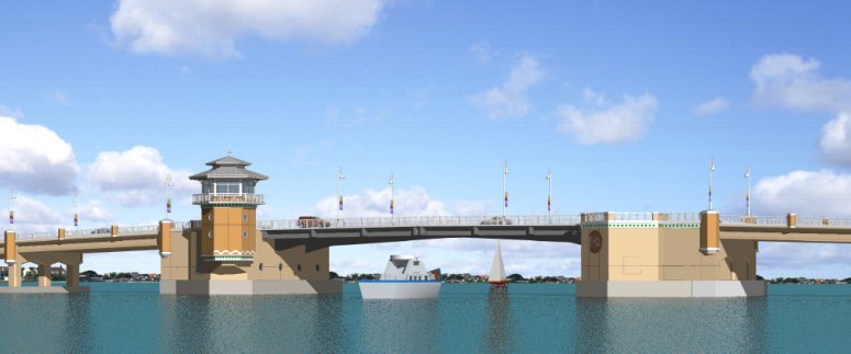
US consultant EC Driver is nationally recognized in the movable bridge industry for its expertise in structural engineering, heavy machinery, control systems and fluid power systems. It operates as a wholly owned sub-division of URS Corporation and uses LUSAS Bridge analysis software to assist with the analysis and design of its movable bridge projects. As well as creating detailed 3D models for new design, EC Driver routinely creates 2D frame analysis models of the main girders of existing bridges to generate moments, shears and reactions for use in load rating analyses. Ocean Avenue Bridge New Ocean Avenue Bridge in Lantana, Florida is currently under construction for Palm Beach County. It replaces a previous crossing, built in 1950, that had effectively come to the end of its service life. The new crossing provides a wider navigation channel and an extra 11 feet of vertical navigational clearance over the previous structure. The deck is also wider at 52 feet, incorporating a new pedestrian walkway and a cycle lane alongside each of the driving lanes. EC Driver used LUSAS to carry out a three-dimensional frame analysis of the double-leaf, trunnion bascule leaves to investigate the forces, moments, shears and reactions in the various members of the complex structure. The bascule leaves of both bascule bridges include a lightweight Exodermic deck that consists of a thin lightweight concrete slab supported on and made composite with a structural steel grid, and where the deck is also made composite with the bascule leaf main girders, floor beams, and stringers. LUSAS was also used to perform finite element analysis of the bascule piers (using both solid element and plate/shell models) to address some challenging structural support and loading conditions.
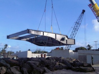
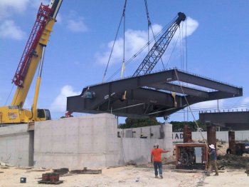
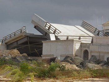
Port Ferdinand Bridge Similar modelling and analysis work was also done on the Port Ferdinand Bridge in Barbados, West Indies, which also used the Exodermic deck system. This twin bascule bridge, spans a 40 feet wide channel connecting the marina lagoon to the Caribbean Sea.
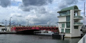
5th Street Bridge, Miami The original 80 year-old Northwest 5th Street Bridge in Miami, Florida, was replaced with a new low-level, double-span bascule bridge with increased navigational clearance. For the new bridge EC Driver carried out a three-dimensional modelling analysis of the bascule leaf framing for a bridge contractor. This analysis was used to estimate the deformations in the steel members during erection with the intent of verifying that the proposed erection scheme would not introduce out of plane deformations in the frames that support the rack gears that were in excess of the tight rack alignment tolerances. The analysis also demonstrated that the bascule leaves could be raised and lowered during erection without introducing excessive deformations and stresses in the steel counterweight box with the top plate of the box removed and large amount of steel ballast in place within the counterweight.
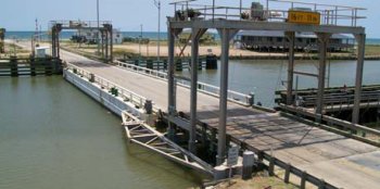
Other projects LUSAS was also used to perform a three-dimensional frame analysis of new hoist frames that support the overhead operating equipment that lifts the apron spans for a floating barge bridge in Sargent Texas for Texas DOT and for a two-dimensional frame analysis of a cable stayed swing bridge concept for the Simpson's Bay Lagoon Bridge in St. Maarten, West Indies. Load rating assessments In addition to the previously described illustrative projects, EC Driver routinely uses LUSAS to perform two-dimensional frame analysis models of the main girders of existing bridges to generate the moments, shears and reactions for use in a load rating analysis. Bridge projects in Florida on which this has been done include:
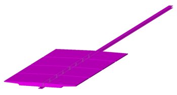
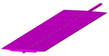
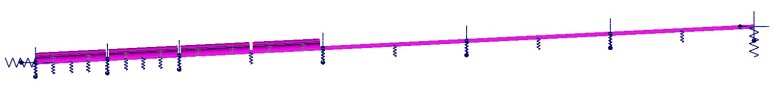
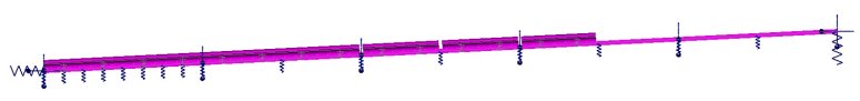
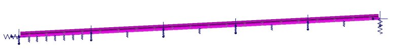
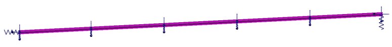
SR-80 Southern Boulevard Bascule Bridge As of August 2012, EC Driver is currently using LUSAS to perform the construction analysis of an incrementally launched, post-tensioned, segmental concrete slab structure for the approach spans of the SR-80 Southern Boulevard Bascule Bridge in West Palm Beach, Florida for the Florida Department of Transportation. The new crossing replaces a previous structure that was built in 1950. It will still carry one lane of traffic in each direction but will provide an increased width for cyclists and pedestrians and an increased width and navigational clearance at the bascule drawbridge for shipping. The bridge superstructure is a post-tensioned slab that will span 72'-0 between piers. It is being designed so that during launching, rather than being directly supported on piers or bents, the segments be supported on steel launching beams to facilitate the introduction of the vertical roadway curve. As a result, the launching method is effectively a hybrid of incremental launching and span-by-span construction. To model this process a detailed staged construction model was created in LUSAS to model all aspects of the proposed launch procedure. Temporary bents were modelled as springs.
LUSAS is also being used on the project to perform an analysis of the bascule leaf main girders to generate the forces and deflections used in the design of these members. There are multiple areas of interest with regard to stress magnitude and distribution around the support and counterweight attachment point of the leaf. Using LUSAS, the design of the flanges, tread, stiffeners, and particularly their termination points, can be examined to avoid any stress concentrations.
Find out more
Other LUSAS Bridge case studies:
|
|
Software Information
|
||||||||||||||||||||||||||||||||||||||||||||||||
|
||||||||||||||||||||||||||||||||||||||||||||||||||